
Key Takeaways
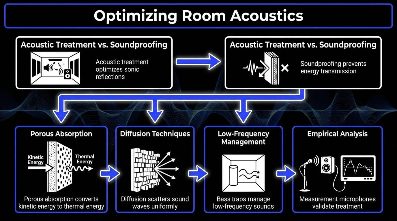
- Acoustic treatment and soundproofing are not the same: treatment improves how sound behaves inside a room, while soundproofing stops sound from entering or leaving the space.
- Low-frequency control is the most important part of studio treatment because bass buildup, room modes, and SBIR can seriously affect mix decisions.
- Thin foam panels are not enough for proper acoustic treatment, since they mostly absorb high frequencies while leaving low and low-mid problems unresolved.
- Proper monitor placement, bass traps, broadband panels, ceiling clouds, and first reflection treatment help create a more accurate listening environment.
- Measurement tools, reference listening, and controlled source material from tools like ACE Studio help producers decide whether a problem comes from the room, the arrangement, or the mix itself.
Introduction to Acoustic Management
Achieving pristine audio accuracy within an enclosed space requires a comprehensive understanding of acoustic physics and architectural design. Sound reproduction within any room is a symbiotic relationship between the monitoring system and the boundaries of the space itself. When a loudspeaker driver shifts to project acoustic energy, the resulting wave travels not only directly to the ears of the listener but also radiates outward to impact the floor, ceiling, and walls. These architectural surfaces reflect, absorb, or transmit the acoustic energy based on their composition and mass.
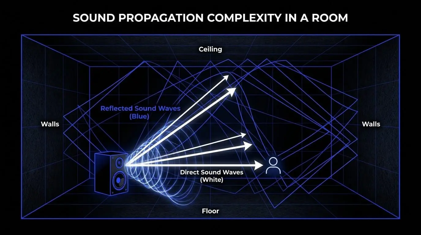
An untreated room behaves like an uncontrolled filter, applying severe frequency distortions, phase cancellations, and temporal smearing to the audio signal. Consequently, an audio engineer or music producer operating within an unmanaged space cannot make accurate decisions regarding equalization, dynamic compression, or spatial positioning. Unmanaged room acoustics can introduce severe frequency anomalies, significantly exaggerating or attenuating low-end frequencies. This discrepancy causes translation failure, where an audio mix sounds perfect within the production environment but completely collapses when played on commercial car stereos, consumer headphones, or club sound systems.
Implementing strategic acoustic room treatment addresses these internal distortions. By deploying specialized mechanical structures designed to absorb or diffuse targeted wave frequencies, the physical space can be transformed into a neutral monitoring environment. The primary objective is not to silence the room completely, but rather to establish a balanced decay time across the entire audible spectrum, ensuring that what emits from the reference monitors is exactly what arrives at the listening position.
The Crucial Distinction: Isolation Versus Internal Treatment
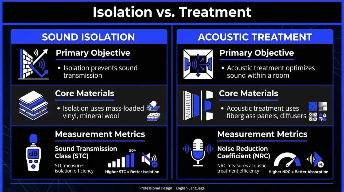
A pervasive misconception within studio design is the conflation of structural soundproofing with internal acoustic room treatment. These two disciplines address entirely distinct physical phenomena and require fundamentally different engineering methodologies, materials, and structural modifications.
Defining Audio Isolation and Acoustic Insulation
Structural isolation, accurately classified as audio isolation or soundproofing, is the mechanical process of preventing sound energy from crossing a specified boundary. This involves either retaining sound within a space to prevent environmental disturbance or excluding external ambient noise from entering a sensitive recording environment. The primary metric for evaluating these systems is the Sound Transmission Class (STC), an integer rating that quantifies how efficiently a building partition attenuates airborne sound.
Achieving high STC values relies on implementing comprehensive acoustic insulation within structural barriers. Sound travels through paths of least resistance; airtight seals and dense barriers are the primary defenses against transmission. For true isolation, an existing structure must be decoupled from the surrounding architecture. Without physical decoupling, kinetic energy impacts a wall, converts into structural vibration, travels through floor joists, and reradiates into adjacent spaces as audible sound.
Noise Reduction Methods and Structural Mass
Effective noise reduction methods targeting structural isolation operate on four fundamental mechanical principles:
- Mass: Utilizing dense, heavy materials such as mass-loaded vinyl (MLV), multiple layers of type-X gypsum board, or solid concrete blocks. High mass increases the inertial resistance of the barrier, making it more difficult for incident sound waves to vibrate the structure.
- Decoupling: Creating mechanical breaks in the construction pathway. This is achieved through the installation of resilient isolation clips, furring channels, or by constructing entirely independent double-stud walls with an isolated air gap. Decoupling stops structural vibrations from conducting across adjacent surfaces.
- Conduction Damping: Applying visco-elastic damping compounds between rigid layers of mass. These specialized compounds act as a mechanical shear layer, converting the kinetic vibrational energy traveling through the drywall into microscopic amounts of thermal energy.
- Absorption Cavity Fill: Filling the internal air gaps of decoupled walls with low-density mineral wool or fiberglass insulation to damp internal cavity resonances and prevent the drum-head resonance effect.
Sound Isolation Strategies for Home Studios
In a standard home recording studio setup, executing structural isolation is challenging due to the architectural constraints of residential buildings. Standard residential walls typically feature single-stud construction with thin drywall, yielding low STC ratings that easily allow low-frequency energy to pass through.
Implementing effective sound isolation strategies in these environments requires a systematic identification of structural weak points. Windows and doors represent the most significant compromises in acoustic insulation. Standard hollow-core residential doors provide virtually no inertial resistance to sound waves. Upgrading to solid-core doors equipped with heavy-duty perimeter neoprene gaskets and drop-down seals at the threshold is an essential first step.
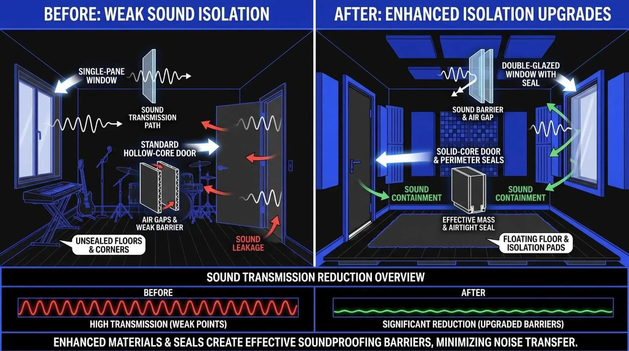
Windows require retrofitting with secondary interior glazing units featuring thick, laminated glass spaced significantly away from the primary window pane to create a decoupled air barrier.
| Mechanical Property | Structural Isolation (Soundproofing) | Internal Acoustic Treatment |
|---|---|---|
| Primary Objective | Attenuation of sound transmission between separate environments. | Optimization of sound wave behavior inside a single environment. |
| Target Locations | Internal wall cavities, doors, windows, floors, and ceilings. | Boundary reflection points, wall faces, corners, and ceiling surfaces. |
| Core Materials | Mass-loaded vinyl, dense mineral wool, resilient clips, green glue. | Porous fiberglass panels, quadratic diffusers, membrane traps. |
| Primary Metric | Sound Transmission Class (STC) / Noise Isolation Class (NIC). | Noise Reduction Coefficient (NRC) / Reverberation Time. |
The Physics of Sound Behavior in Enclosed Spaces
When sound waves propagate from a source within an enclosed space, they interact continuously with the room boundaries until their energy completely dissipates. Understanding these interactions requires analyzing the physical properties of sound waves as they transition from free-field propagation to bounded-space behavior.
Sound Absorption Solutions and Materials
When a sound wave encounters an obstacle or boundary, its energy splits into three distinct components: transmitted energy, reflected energy, and absorbed energy. Mechanical sound absorption solutions focus on maximizing the absorbed component by converting acoustic kinetic energy into thermal energy.
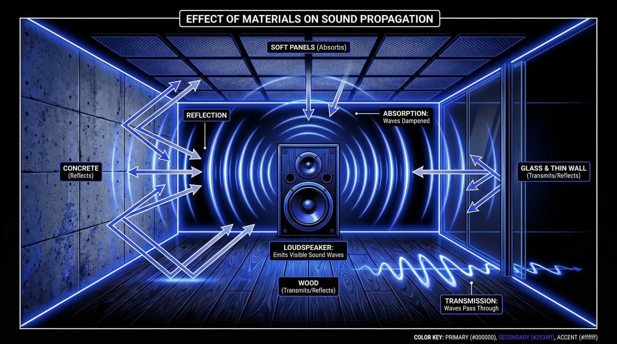
Porous sound absorption relies on open-cell materials such as industrial fiberglass or semi-rigid mineral wool. As sound waves strike these materials, the moving air molecules penetrate the complex, interconnected matrix of fibers. The friction generated between the moving air particles and the physical fibers slows the molecular velocity, effectively transforming the kinetic energy of the wave into heat.
The performance of these sound absorption solutions depends heavily on material thickness and density. For a porous absorber to effectively attenuate a specific frequency, its thickness must correspond significantly to the particle velocity component of the wave. Sound wave velocity is at its maximum at a distance equal to one-quarter of its wavelength from a reflective boundary, while sound pressure is at its maximum directly at the boundary wall.
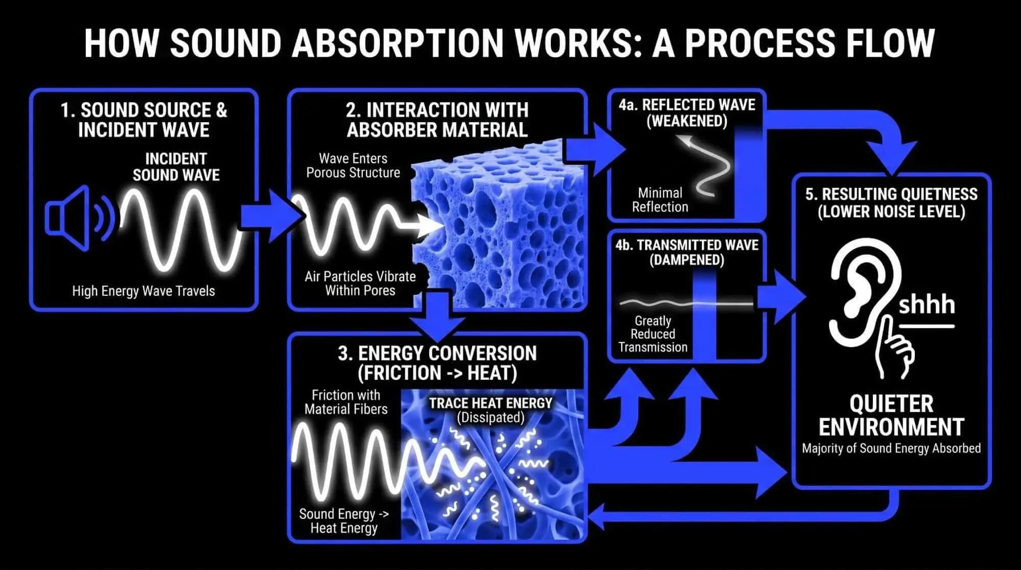
Because low-frequency waves have long physical wavelengths extending several meters, their peak velocity zone occurs relatively far from structural boundaries.
Conversely, air particles slow down to near-zero velocity directly at the face of a solid wall. Consequently, a thin porous panel attached directly to a wall has almost no effect on low frequencies because it sits entirely within the zero-velocity zone. Treating long wavelengths requires utilizing thick porous material or spacing the treatment away from the wall to align the core insulation with the high-velocity zones of the wave.
The Mechanics of Wave Diffusion
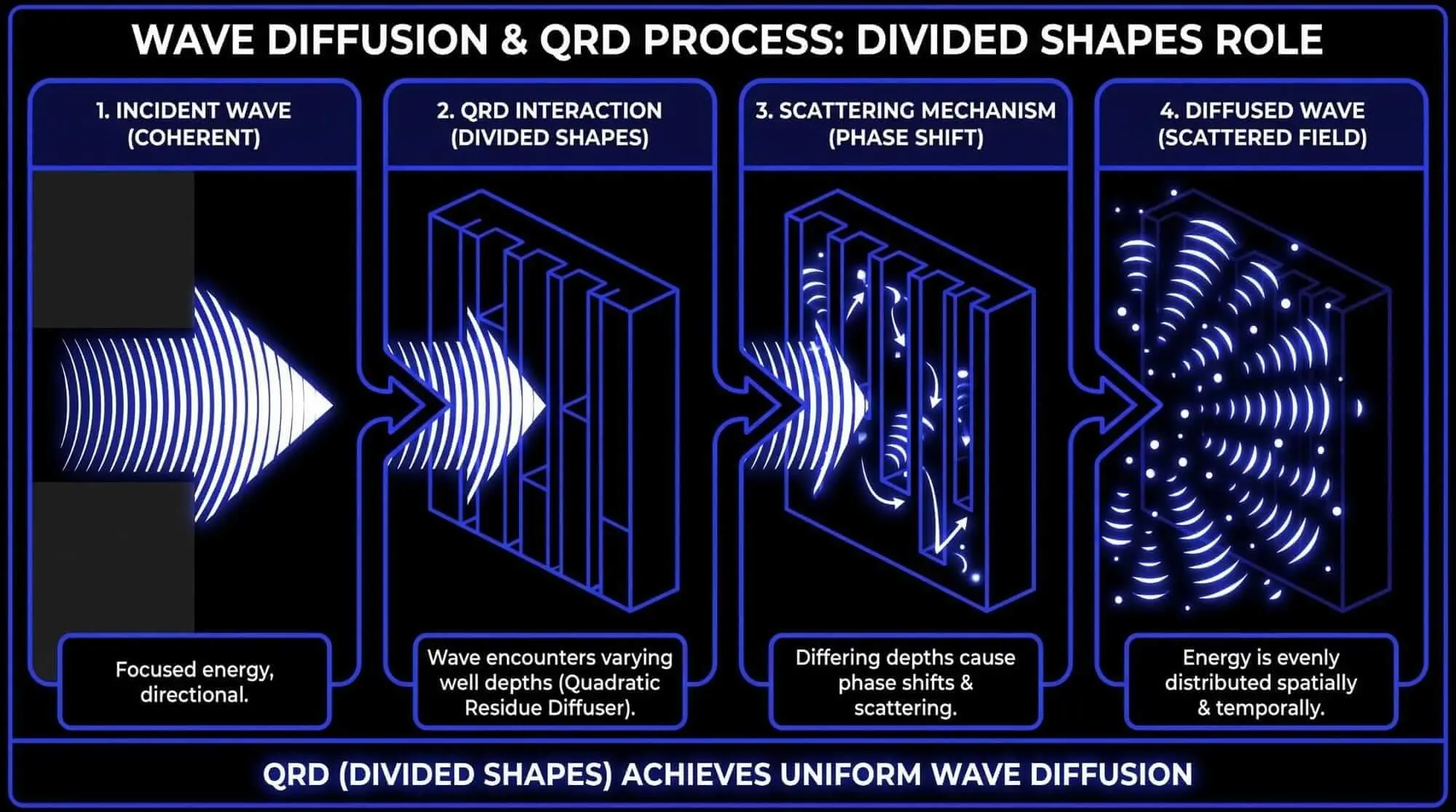
While absorption removes energy from the room, over-absorbing mid and high frequencies can result in an unnatural listening environment. To prevent this issue without causing destructive reflections, engineers utilize studio acoustics diffusers.
Diffusion is the process of scattering incident sound waves uniformly across both time and space. When a sound wave strikes a flat, reflective surface, it undergoes specular reflection, where the angle of reflection equals the angle of incidence. This creates concentrated, localized reflections that cause phase cancellation and echo anomalies. A diffuser breaks up these reflections by utilizing uneven surface topography designed around mathematical sequences.
The most widely deployed diffusers are Quadratic Residue Diffusers (QRD). These units consist of a series of wells of varying depths separated by thin rigid dividers. The depths of these wells are calculated using number theory formulas based on prime numbers.
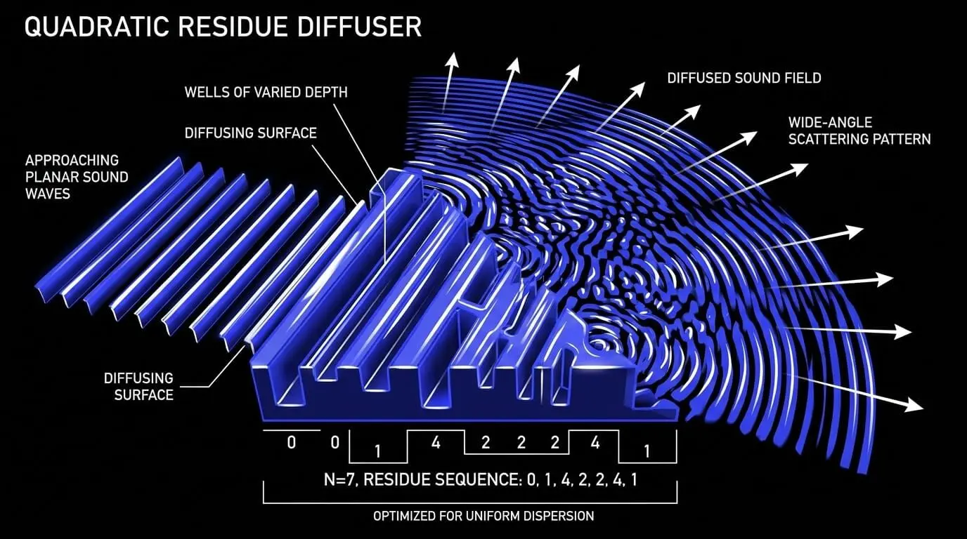
When a broad wave strikes a quadratic diffuser, the varying well depths introduce distinct phase shifts across the reflected energy components. The wavefront exits the diffuser scattered across a wide, radial arc rather than returning as a single coherent reflection. This process preserves the acoustic energy within the room, maintaining spatial airiness and life while eliminating harmful specular distortions.
The Phenomenon of Echo Control and Reverberation Control
Two major issues that degrade audio clarity within untreated spaces are flutter echoes and excessive reverberation times. Flutter echo occurs when short, high-frequency sound bursts bounce rapidly between two parallel, highly reflective walls. This produces a distinct, metallic ringing or clicking sound that colors recordings and ruins monitoring accuracy. Resolving this issue requires applying targeted echo control by adding absorption or diffusion to at least one of the parallel surfaces to disrupt the continuous reflection loop.
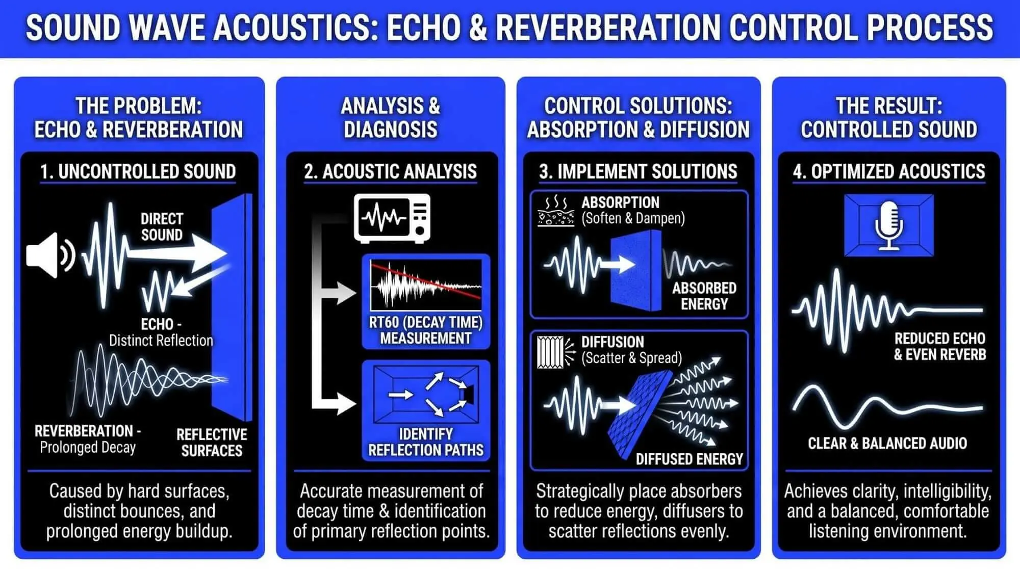
Reverberation time is the time required for the sound pressure level within a space to decrease by sixty decibels after the initial sound source has ceased. In large, hard-surfaced spaces, this decay time can easily exceed several seconds, causing subsequent sound waves to overlap and mask fine details. Achieving precise reverberation control means implementing calculated acoustic treatment to lower the room's decay time to an optimal range based on its intended use:
- Voiceover and Tracking Booths: Extremely controlled to capture completely dry, uncolored signals.
- Stereo Mixing and Mastering Environments: Moderately controlled to balance spatial imaging accuracy with a natural room feel.
- Home Theater Environments: Well-balanced to support multichannel surround systems and localized spatial steering.
Strategic Planning and Room Analysis
Treating a room without pre-production analysis can lead to poor performance and wasted budget. A systematic approach to room optimization requires defining performance criteria and performing acoustic calculations before installing any panels.
Defining Room Purpose and Audio Goals
Acoustic priorities vary significantly depending on the creative tasks being performed within the space:
- Electronic Music Production: Requires critical low-end control down to the lowest sub-bass registers. This demands substantial low-frequency trapping to accurately manage sub-bass transients.
- Acoustic Tracking and Voice Recording: Prioritizes tracking cleanliness and isolation from ambient noise. The focus centers on eliminating mid-frequency vocal boxiness and high-frequency flutter echo.
- Critical Mastering Labs: Requires an exceptionally flat frequency response across the entire audible spectrum, alongside balanced decay times and an uncompromised stereo field.
Dimensional Analysis and Frequency Analysis
Every physical enclosed space possesses a unique set of natural resonant frequencies known as room modes. These modes occur when the distance between parallel walls matches multiples of a sound wave's half-wavelength, causing the wave to reflect back upon itself and form a standing wave. Standing waves create fixed areas of high and low sound pressure throughout the room, resulting in severe volume peaks and deep nulls at specific frequencies.
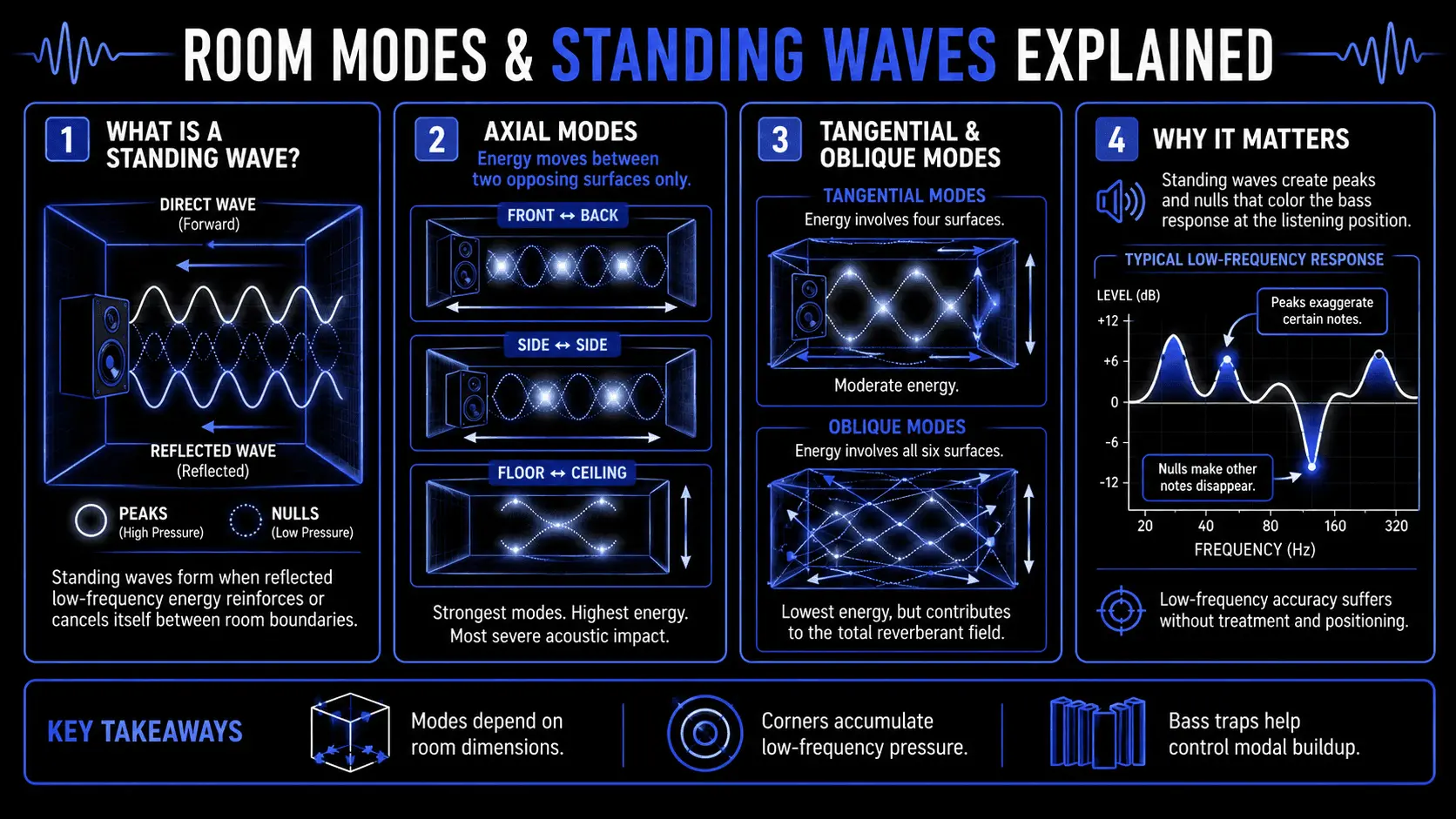
Room modes are categorized into three distinct wave topologies:
- Axial Modes: Produced between two opposing parallel surfaces (front-to-back, side-to-side, or floor-to-ceiling). These contain the highest energy and cause the most severe acoustic distortions.
- Tangential Modes: Involve four reflecting surfaces, looping around the room perimeter. They carry roughly half the energy of axial modes.
- Oblique Modes: Involve all six surfaces of the room. They possess the lowest energy but contribute to the overall reverberant field.
To predict where these standing waves will develop, engineers perform a frequency analysis based on the physical dimensions of the room. The physical length, width, and height of a rectangular space dictate which specific sound wavelengths will structurally reinforce or cancel themselves when bouncing between opposing boundaries.
Identifying Room Modes and Boundary Interference
When evaluating low-frequency anomalies, engineers must also account for Speaker Boundary Interference Response (SBIR). SBIR occurs when low-frequency waves radiate omnidirectionally from a monitor housing, strike the wall behind the speaker, and reflect forward to combine with the direct signal. Because of the physical distance delay, specific frequencies will arrive exactly out of phase with the direct speaker radiation, creating deep, sharp frequency nulls that cannot be corrected via electronic equalization.
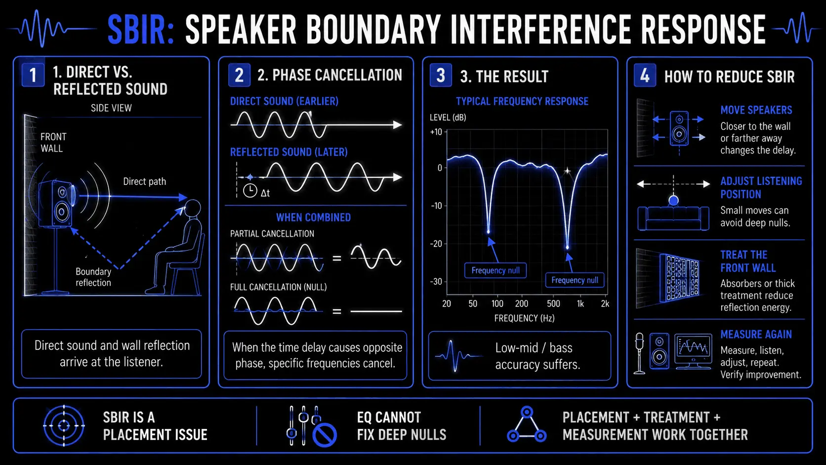
To mitigate SBIR and room mode anomalies, engineers analyze the acoustic transition zone defined as the Schröder Frequency. The Schröder Frequency marks a physical boundary where a room transitions from behaving as individual, distinct low-frequency resonances to behaving as a dense, complex, and diffuse reverberant field. Frequencies falling below this transitional threshold require heavy, targeted pressure or velocity treatment. Frequencies above this threshold can be managed with thinner, broadband geometric panels.
The Step-by-Step Treatment Implementation Workflow
Transforming a room requires following a precise installation workflow to ensure each acoustic component functions optimally within the space.
Selecting Acoustic Treatment Materials
A common mistake in a home recording studio setup is relying on low-density open-cell acoustic foam panels. These lightweight foam shapes offer poor gas flow resistance and lack the mass required to absorb low frequencies. While they can attenuate high frequencies, they leave low and low-mid frequencies uncontrolled, resulting in a room that feels dull in the high frequencies but remains muddy and boomy in the low end.
High-performance systems use specialized industrial acoustic treatment materials categorized by their density and gas flow resistance metrics:
- Rigid Fiberglass: Industrial standard glass-fiber boards. Medium-density options are highly effective for broadband panels, while ultra-high-density boards excel at managing lower frequencies when deployed in thick configurations.
- Semi-Rigid Mineral Wool: An excellent stone wool alternative. It offers exceptional absorption coefficients per dollar and features natural fire-resistant properties.
- Limp Mass Membrane Layers: Non-porous sheet materials suspended inside panel enclosures to react to high sound pressure zones, converting low-frequency acoustic energy into mechanical movement.
Low-Frequency Management and Bass Traps
Because low frequencies carry high energy and accumulate along room boundaries, treating them is the most critical step in room tuning. Specialized bass traps must be deployed in high-pressure zones where room modes intersect—most notably in the vertical and horizontal corner intersections of the room.
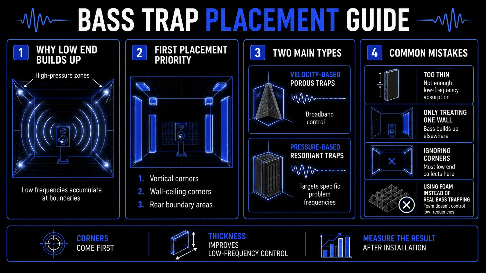
There are two primary styles of low-frequency traps:
- Velocity-Based Porous Traps: Thick, triangular stacks of mineral wool or fiberglass placed directly in corners. They operate by capturing air molecules at their maximum velocity as they attempt to move away from the corner boundary.
- Pressure-Based Resonant Traps (Sealed Membranes and Resonators): Tuned structures designed to target specific modal frequencies. A membrane absorber uses a sealed airtight box with a flexible front diaphragm. The physical thickness of the air cavity and the total surface weight of the front face dictate the exact frequency targeted by the trap, allowing the diaphragm to move in sympathy with specific problem frequencies and convert that pressure energy into mechanical displacement.
Early Reflection Points and Panel Deployment
Once corner low-frequency management is secure, the next phase focuses on treating early reflection points. These are the specific areas on the side walls, floor, and ceiling where sound waves bounce directly from the monitors to the ears of the listener, arriving immediately after the direct signal. These reflections combine with the direct sound to cause comb filtering, which degrades stereo imaging and distorts high-frequency response.
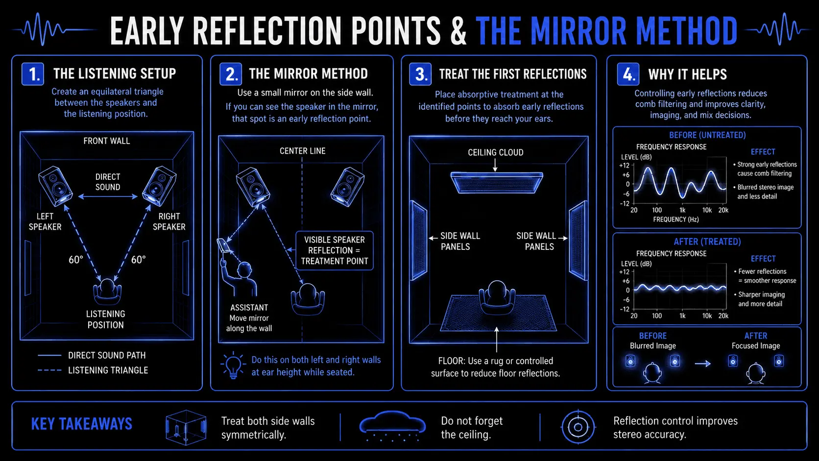
Finding these zones can be accomplished using a mirror:
- The listener sits at the primary monitoring position.
- An assistant slides a flat mirror along the side wall surface at ear height.
- The spot where the listener can see the reflection of the loudspeaker driver in the mirror marks an early reflection point.
A thick broadband absorption panel must be installed at this location to absorb the mirror reflection. This process is repeated for both side walls and the ceiling area between the listener and the monitors. The treated ceiling area is commonly referred to as a ceiling cloud.
Speaker and Listener Positioning Optimization
No amount of treatment can fix an environment where the monitoring position is placed within a severe modal node. Before installing permanent treatments, engineers configure the room geometry based on established layout principles:
- The 38% Placement Metric: Along the center line of a rectangular room, positioning the listener's head at a distance equal to roughly 38% of the total room length from the front wall helps avoid the worst peak and null zones of primary longitudinal room modes.
- Equilateral Monitoring Triangle: The distance between the left and right high-frequency drivers must exactly equal the distance from each driver to the center axis of the listener's head. This layout creates an accurate 60-degree stereo image.
- Acoustic Axis Alignment: High-frequency drivers must be elevated and angled to align directly with the listener's ears, as high frequencies project in highly directional wave patterns.
DIY Implementation and Cost-Effective Sourcing
Building custom acoustic treatments can save significant budget compared to purchasing pre-assembled commercial panels. This approach allows users to build thicker, high-performance panels tailored to their specific room dimensions.
Building Custom Panels Using Mineral Wool and Rockwool
Constructing high-performance broadband panels using semi-rigid mineral wool boards requires basic woodworking tools and appropriate safety equipment:
- Frame Construction: Build a four-sided outer frame using lightweight timber or plywood. Ensure the internal dimensions match standard insulation boards. Drill large ventilation holes through the side frame segments to allow sound waves to penetrate the sides of the panel, increasing overall acoustic efficiency.
- Insulation Sizing: Insert a thick slab of mineral wool or fiberglass into the frame cavity. To handle lower frequencies, combine multiple layers to create an exceptionally deep panel.
- Fabric Covering: Wrap the assembly in an acoustically transparent fabric. The transparency of a fabric can be tested by holding it to the mouth and breathing through it. If air passes through without noticeable resistance, the fabric will allow sound waves to pass into the internal insulation material rather than reflecting off the surface. Secure the fabric tightly to the back of the wood frame using heavy-duty staples.
- Air Gap Mounting: When hanging the panels, mount them with a spacing distance from the wall equal to the thickness of the panel itself. This layout shifts the porous material forward into zones of higher wave velocity, significantly increasing the panel's low-frequency performance without requiring additional insulation material.
Sourcing Budget-Friendly Noise Reduction Materials
For projects with limited budgets, sourcing materials through non-traditional audio channels can help keep costs low:
- Industrial Insulation Distributors: Sourcing mineral wool or fiberglass boards directly from commercial construction insulation distributors rather than retail audio outlets can reduce material costs significantly.
- Heavy Cotton Moving Blankets: While moving blankets cannot replace thick bass traps, layering dense cotton moving blankets can provide effective high-frequency audio dampening techniques for temporary vocal tracking setups.
- Second-Hand Online Marketplaces: Commercial facilities undergoing remodeling often sell large quantities of used acoustic panels, diffusers, and mass-loaded vinyl at deep discounts.
The Risks of All-In-One Consumer Packs
Many budget consumer acoustic kits feature thin, sculpted foam squares. These products are generally ineffective for comprehensive room optimization. Because they can only absorb high frequencies, installing them across a room leaves the low-mid and low frequencies completely untouched. This creates an unbalanced environment that lacks top-end life but suffers from severe low-frequency muddiness, making accurate audio monitoring difficult.
Testing, Verification, and Fine-Tuning
Acoustic room treatment is an iterative engineering process. Once structural treatments are installed, the environment must be tested using specialized software to measure its performance and guide final adjustments.
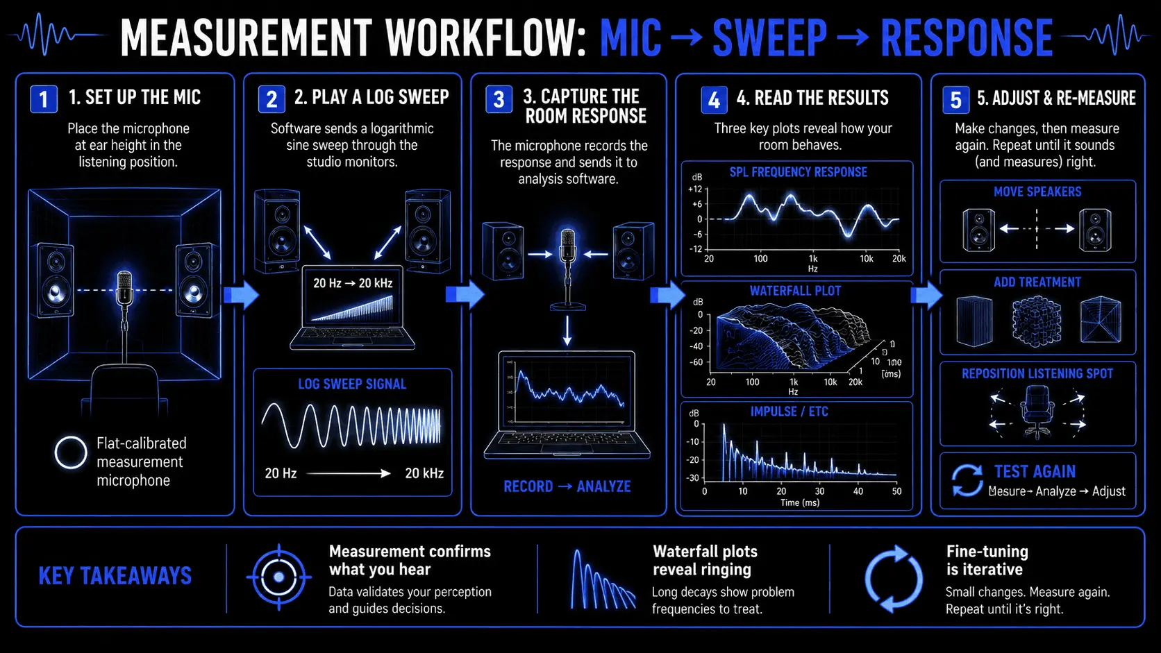
Acoustic Measurement Software and Hardware Setup
Analyzing a room requires an omnidirectional measurement microphone with a flat calibration profile paired with dedicated analysis software.
The testing process follows a standard procedure:
- Mount the measurement microphone at the primary listening position, positioned at ear height and oriented vertically toward the ceiling at a 90-degree angle.
- Configure the software to output a long logarithmic sine-wave sweep spanning from the lowest sub-bass frequencies up to the limit of human hearing through the reference monitors.
- The microphone captures the room's response to the sweep, allowing the software to calculate the room's precise impulse response.
Iterative Adjustments and Micro-Positioning
The data captured by the analysis software generates three primary diagnostic plots:
- The SPL Frequency Response Curve: Reveals the location of modal peaks and cancellation nulls across the frequency spectrum.
- The Waterfall Plot: Displays the time-domain decay across frequencies. This plot highlights modal ringing, showing which specific low frequencies continue to resonate over time.
- The Impulse Response / Envelope Time Curve (ETC): Measures the arrival time of distinct reflections relative to the direct signal, allowing engineers to pinpoint untreated early reflection points.
If the waterfall plot shows significant resonance tailing in the low end, corner bass traps must be expanded or moved to high-pressure boundaries. If the plot shows sharp energy spikes within the first 15 milliseconds, the side panels or ceiling cloud must be adjusted to better cover the early reflection paths. Moving monitors closer to or farther from the front wall by minor increments can significantly alter the interference profile, helping flatten the low-mid frequency response.
How ACE Studio Helps You Make Better Production Decisions in a Treated Room
Acoustic room treatment helps your room tell the truth. Bass traps reveal low-end buildup more clearly. Broadband panels reduce early reflections. Diffusion helps preserve space without letting hard reflections smear the stereo image. Once the room becomes more balanced, you can hear the difference between an acoustic problem and a musical problem.
That distinction matters. A muddy chorus is not always caused by bad room modes. Sometimes the bass part is too busy. Sometimes the kick and low strings are fighting for the same space. Sometimes the vocal stack feels cloudy because every harmony is delivering the same consonants with the same timing. Acoustic treatment improves what you hear, but the arrangement still needs to be shaped.
ACE Studio is useful at that exact point. It gives producers a controlled way to rebuild, test, and refine musical parts once the room is honest enough to expose what is really happening.
In a partially treated room, it can be difficult to know whether a problem comes from the space or from the source material. ACE Studio helps by letting you create cleaner, more repeatable parts from MIDI, lyrics, stems, and audio ideas. You are not guessing from a messy demo recorded in a reflective corner. You can isolate the musical idea, reshape it, and listen again with more confidence.
For example, if a vocal demo sounds boxy in a small room, the room may be exaggerating low-mid reflections. But the part itself may also have too much tension, too much chest tone, or stacked syllables that crowd the mix. Its AI Singing Voice Generator, lets you shape the vocal line at the note, lyric, pronunciation, pitch, and expression level before deciding how much of the problem belongs to the room. That makes acoustic treatment decisions more practical because you are not judging the space from an uncontrolled recording.
The same applies to instruments. Its AI Instruments let you turn MIDI into expressive instrumental parts, which can help you test arrangement density without recording more material into the room. If you are checking whether your low end translates better after adding bass traps, a controlled bass, cello, or layered instrumental part gives you something consistent to evaluate. If the room still rings at certain notes, you will hear it. If the arrangement itself is too crowded, you will hear that too.
Stem Splitter is especially useful when working with rough demos. A full stereo bounce can hide the cause of a problem. Once separated into vocals, drums, bass, piano, guitar, and other elements, it becomes easier to ask better questions:
This is not a replacement for acoustic measurement software, a calibrated microphone, or physical room treatment. You still need bass traps, proper monitor placement, reflection control, and verification with real measurements. ACE Studio simply gives you better musical material to judge once those physical changes are in place.
That can save a lot of frustration. Instead of moving panels because one rough demo sounds muddy, you can separate the stems, rebuild the problem section, or create a cleaner reference part. Instead of assuming your room is ruining the vocal, you can adjust the phrasing, pronunciation, and layer balance first. Instead of recording new strings or choir parts in a space that is not ready, you can shape them inside ACE Studio and focus on how they sit against the treated room.
A practical use case looks like this:
- Treat the main room problems first: corners, first reflection points, speaker placement, and ceiling reflections.
- Play a rough mix and identify what still feels unclear.
- Use ACE Studio to separate or rebuild the part causing the issue.
- Listen again in the treated room.
- Decide whether the next move is acoustic, musical, or mix-related.
That last step is the real advantage. Acoustic room treatment gives you a more accurate space. ACE Studio gives you more control over the material you are judging inside that space. Together, they help you make decisions based on the song itself – not just the flaws of the room, the recording, or the first rough demo.
Common Failures and Pitfalls in Studio Design
Avoiding common acoustic design mistakes saves time and prevents performance bottlenecks:
- Over-Dampening High Frequencies: Covering every square inch of wall space with thin absorption materials removes too much high-frequency energy while leaving low-frequency modes active. This results in an unbalanced, unnatural environment. Treatment should be distributed between absorption and diffusion to maintain natural room ambiance.
- Misplacing Bass Traps: Installing porous traps only in areas where wall pressure is low reduces their performance. Low-frequency traps must be placed in high-pressure boundary zones, specifically corners, where they can interact with maximum modal energy.
- Symmetrically Distorting Layouts: Setting up a monitoring station off-center relative to the side walls creates asymmetrical early reflections. This causes the left and right monitors to sound distinct from one another, unbalancing the stereo image and affecting pan decisions.
- Relying on Digital Software Calibration Alone: Attempting to correct deep phase cancellations and modal nulls using digital software equalization does not fix the underlying physical room reflections. Because nulls are caused by phase cancellation, boosting the frequency electronically increases both the direct sound and the cancellation reflection, wasting amplifier headroom without filling the frequency drop. Digital correction should only be used to fine-tune a room after physical acoustic treatments have been optimized.
Frequently Asked Questions
Can I completely soundproof a room using acoustic panels?
No. Acoustic panels are designed to absorb internal reflections and improve sound quality within a single room. They lack the structural mass and decoupling required to isolate sound and prevent it from traveling between different spaces.
What is the difference between open-cell foam and mineral wool?
Open-cell foam is lightweight and typically only effective at absorbing high frequencies. Mineral wool is significantly denser, offering high gas flow resistance that allows it to absorb a wider range of frequencies, including critical low and mid-range bands.
How much area inside my room needs to be covered with acoustic treatment?
For standard mixing environments and home studios, covering roughly one-third to nearly half of the total wall and ceiling surface area with targeted treatments is generally sufficient. Tracking booths intended for dry vocal recording may require higher coverage.
Where should bass traps be placed first?
Bass traps should be installed in the vertical corner intersections of the room first, as low-frequency energy and sound pressure naturally accumulate at these primary room boundaries.
How do I fix a deep frequency drop at my listening position?
Deep drops are typically caused by phase cancellations from room modes or Speaker Boundary Interference Response (SBIR). To resolve a drop, try adjusting the physical position of your monitors and listening chair, or install thick bass traps at the reflecting boundaries responsible for the cancellation.
Is it better to use absorption or diffusion on the rear wall?
In small rooms, absorption is preferred because diffusers require physical distance for the scattered wavefront to blend naturally before reaching the listener. In larger rooms, diffusion is ideal on the rear wall to help preserve natural ambiance while breaking up specular reflections.