
Key Takeaways
- Subtractive synthesis starts with a harmonically rich sound and removes selected frequencies with filters to create the desired tone.
- Its core signal path moves from oscillators and noise sources through a filter and amplifier, while envelopes and LFOs control movement over time.
- Waveform choice shapes the starting character: sawtooth waves are bright and dense, square waves sound hollow, triangle waves are softer, and sine waves provide clean low end.
- Filters, ADSR envelopes, resonance, detuning, and modulation can transform simple waveforms into basses, leads, pads, percussion, and evolving textures.
- Producers can expand subtractive sound design beyond traditional oscillators by filtering, layering, and resampling expressive instrument or generated audio from tools such as ACE Studio.
Core Principles of Audio Synthesis
The field of electronic music production relies heavily on the manipulation of electrical signals or digital algorithms to generate acoustic energy. At the foundation of this discipline is the sound synthesis technique, a process that allows sound designers and audio engineers to construct audible timbres from fundamental physical properties. To fully comprehend how electronic music is built, one must explore the fundamental physics of sound and how various audio synthesis methods manipulate frequency, amplitude, and phase over time.
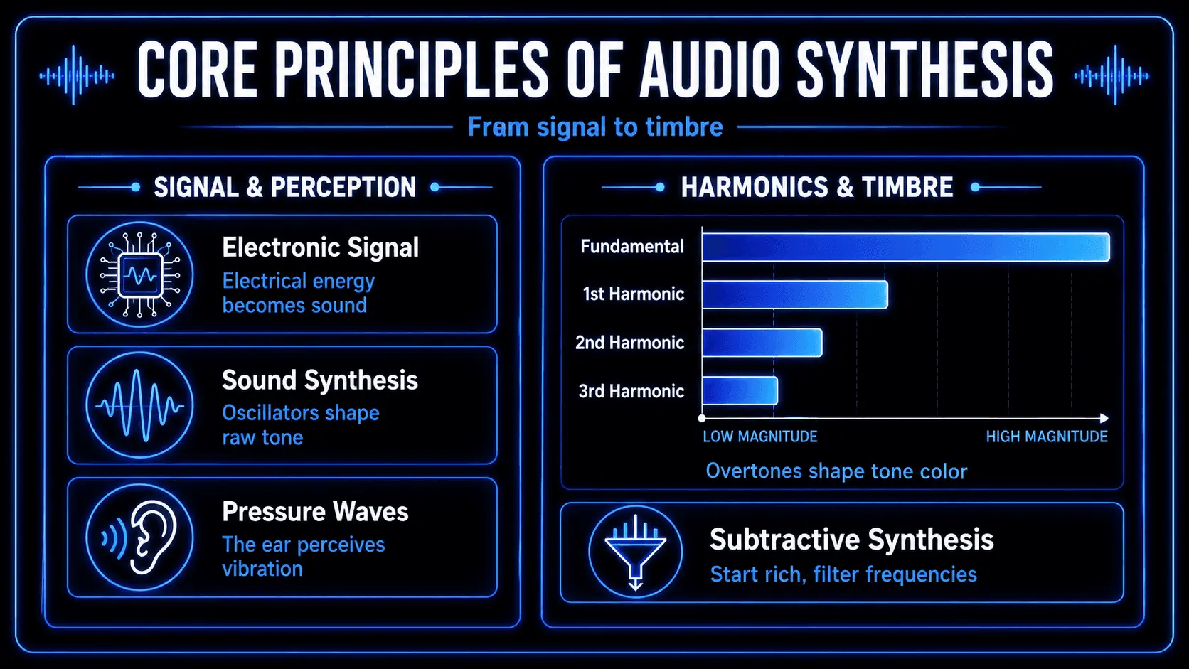
Every sound perceived by the human ear consists of pressure waves vibrating through a medium. These waves are comprised of a fundamental frequency, which determines the perceived pitch, and additional higher frequencies known as overtones or harmonics. The specific configuration, volume, and distribution of these harmonics define the timbre or color of a sound. It is this harmonic structure that allows a listener to distinguish between a violin and a trumpet playing the exact same musical note.
Subtractive synthesis is one of the oldest and most intuitive audio synthesis methods. The core principle governing this approach is the process of subtracting sound. Rather than building a complex sonic profile by piling individual frequencies on top of one another, this method begins with an electronically generated raw signal that is intentionally overloaded with harmonic data. The audio engineer then uses specialized corrective and creative tools to carve away, damp, or completely isolate specific frequency bands.
This process is directly analogous to physical sculpture. An artist does not construct a marble statue by fusing thousands of tiny pebbles together; instead, they select a massive, dense block of stone and use a chisel to chip away excess material until the desired form emerges. In a subtractive synthesizer, the raw oscillator acts as the unformed stone block, and the filter assembly serves as the chisel. By systematically removing harmonic clutter, the sound designer shapes the final audio output with immense precision.
Comparative Analysis of Audio Synthesis Methods
To appreciate the efficiency of subtracting sound, it is useful to contrast it with alternative sound generation paradigms, most notably additive synthesis. While both methods serve the ultimate goal of timbre creation within electronic music production, their technical execution and workflows are diametrically opposed.
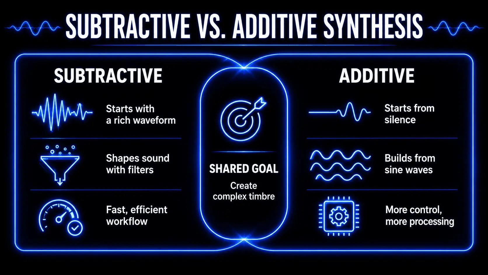
Additive synthesis operates on the principles established by the Fourier theorem, which dictates that any complex periodic waveform can be broken down into a series of individual, pure sine waves. Consequently, an additive synthesizer constructs sound from absolute silence. The instrument introduces a single sine wave at the fundamental frequency and then adds successive sine waves at higher frequencies, meticulously adjusting the amplitude and phase of each discrete component over time.
While additive synthesis offers unparalleled theoretical control over the harmonic spectrum, it presents massive operational challenges. Recreating even a simple acoustic texture requires the simultaneous management of dozens, sometimes hundreds, of independent sine wave generators. For many decades, this made additive systems computationally prohibitive in the digital realm and wildly impractical to construct using analog components.
Subtractive systems circumvent this complexity by reversing the workflow. By utilizing oscillators that natively output complex geometric shapes, the instrument instantly provides all the necessary harmonic material. The engineer does not need to balance individual overtones manually; instead, they apply a filter to alter entire regions of the frequency spectrum at once. This structural efficiency explains why early hardware designers favored subtractive architectures, cementing the method as the absolute standard for sound engineering.
Modern digital tools have introduced further variations, such as frequency modulation and wavetable synthesis. Frequency modulation creates complex harmonics by rapidly modulating the frequency of one oscillator with another, producing highly digital, metallic textures. Wavetable synthesis relies on cycling through a series of static single-cycle audio frames to achieve evolving sounds. Despite these innovations, subtractive principles remain foundational, as almost all frequency modulation and wavetable instruments route their final complex signals through a subtractive filter and amplifier stage to finalize the texture.
Architecture and Signal Path of a Subtractive Synthesizer
The internal routing of a subtractive instrument dictates how an audio signal changes from its inception to its final output. Understanding this path is critical for troubleshooting patches and executing precise sound design techniques. The standard path is sequential, moving from a state of maximum harmonic chaos to a state of controlled acoustic expression.
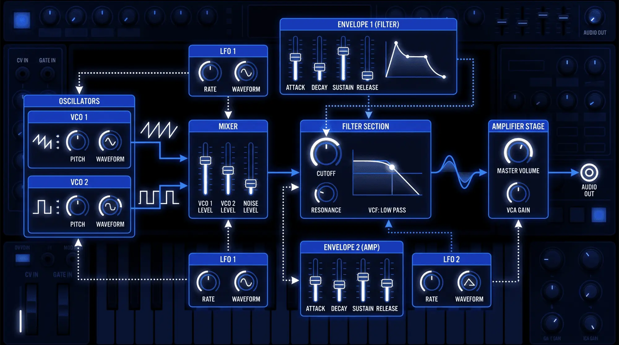
The signal flow begins within the audio generation stage, populated by one or more oscillators and occasionally a noise generator. These components run continuously, generating raw, unshaped electrical currents or digital streams. If multiple sources are active, their outputs are routed directly into a central mixer section, where the relative volume levels of each waveform are balanced against one another.
From the mixer, the summed audio signal enters the filter section. This is the structural heart of filter synthesis, where the primary tonal transformation occurs. The filter alters the frequency response of the collective signal based on user configurations, dulling bright sounds or isolating specific frequency bands.
Once the frequency spectrum has been shaped by the filter, the audio signal proceeds directly to the amplifier stage, often referred to as the voltage-controlled amplifier or digital amplifier. This section regulates the overall amplitude or volume of the sound. Without the amplifier section, the oscillators would produce a continuous, never-ending drone. The amplifier acts as a gatekeeper, ensuring that sound is only heard when a note event is triggered.
Parallel to this primary audio path runs the modulation matrix. Modulation sources, such as envelope generators and low-frequency oscillators, do not generate audible sound themselves. Instead, they produce control voltages or digital control signals that are mapped directly to parameters along the audio path. An envelope might be assigned to open the filter cutoff, while a low-frequency oscillator might modulate the pitch of an oscillator, creating a complex network of moving parts that breathes life into the electronic signal.
Primary Sound Sources: Oscillators and Waveform Selection
An oscillator is the foundational component responsible for creating the initial raw sound wave within a synthesizer. In the analog domain, these components utilize voltage-controlled circuitry to produce a rapidly alternating current. In digital environments, math algorithms compute the geometric coordinates of the wave in real time. The choice of oscillator types directly dictates the initial harmonic potential of a patch.
Standard Waveform Geometries
The specific geometric shape of a periodic waveform determines its harmonic density. Subtractive synthesis relies on several standard shapes, each possessing unique mathematical properties and acoustic profiles.
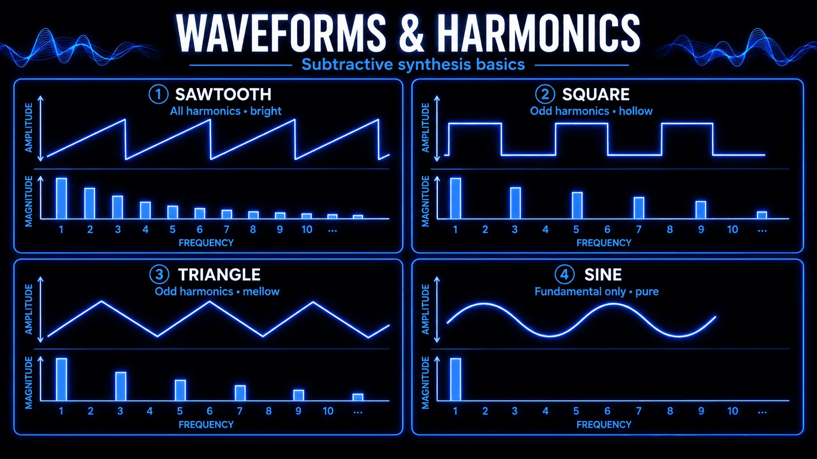
The sawtooth wave is the most versatile option available in subtractive sound design. Its shape resembles the teeth of a mechanical saw, characterized by a sharp linear rise followed by an instantaneous vertical drop. Mathematically, a sawtooth wave contains the fundamental frequency and every single integer multiple overtone above it. The volume of these harmonics decreases at an inverse rate relative to their position in the spectrum. Because it contains both even and odd harmonics across the entire frequency range, it sounds incredibly bright, buzzy, and full, making it the ideal starting material for cutting lead lines, dense brass emulations, and heavy bass sounds.
The square wave presents a geometry that alternates instantly between two fixed amplitudes, spending an equal duration at the maximum positive and maximum negative values. This equal distribution is known as a fifty percent duty cycle. Tonal analysis reveals that the square wave contains only the fundamental frequency and its odd-numbered harmonics. The absence of even harmonics gives the square wave a distinct hollow, woody, or reedy timbre. It is highly valued for creating driving, hollow basslines, chiptune leads, and convincing clarinet emulations.
By altering the duty cycle of a square wave so that it spends unequal time at the top and bottom values, it transforms into a pulse wave. As the pulse width becomes narrower, the lower harmonics drop in volume while the higher harmonics become prominently sharp and nasal. This process of waveform manipulation allows for highly dynamic tonal shifts before the signal even reaches the filter section.
The triangle wave features a symmetrical, linear rise and fall, appearing as a sequence of perfect triangles. Like the square wave, it contains only the fundamental frequency and odd harmonics. However, the amplitude of these overtones drops off exponentially faster. The higher harmonics are so quiet that the triangle wave sounds distinctly muted and round, retaining just enough harmonic edge to remain audible in the upper-midrange. This makes it highly effective for designing soft woodwinds, clean sub-bass foundations, or the core of a mellow pad.
The sine wave represents the absolute purest form of acoustic energy, consisting entirely of the fundamental frequency with zero additional overtones. Because it lacks any harmonic complexity, it cannot be altered by a subtractive filter; there are simply no overtones to subtract. While it cannot serve as raw material for deep filter synthesis, it is vital for generating clean, unadulterated low-end energy, such as sub-bass frequencies that need to pass through a mix without causing upper-frequency clutter.
Noise Generation and Noise Shaping
In addition to periodic geometric waveforms, subtractive synthesis frequently employs a dedicated noise generator. Noise is a non-periodic audio signal, meaning it lacks a repeating pattern and therefore has no identifiable musical pitch. Instead, it consists of a completely random distribution of frequencies across the audio spectrum.
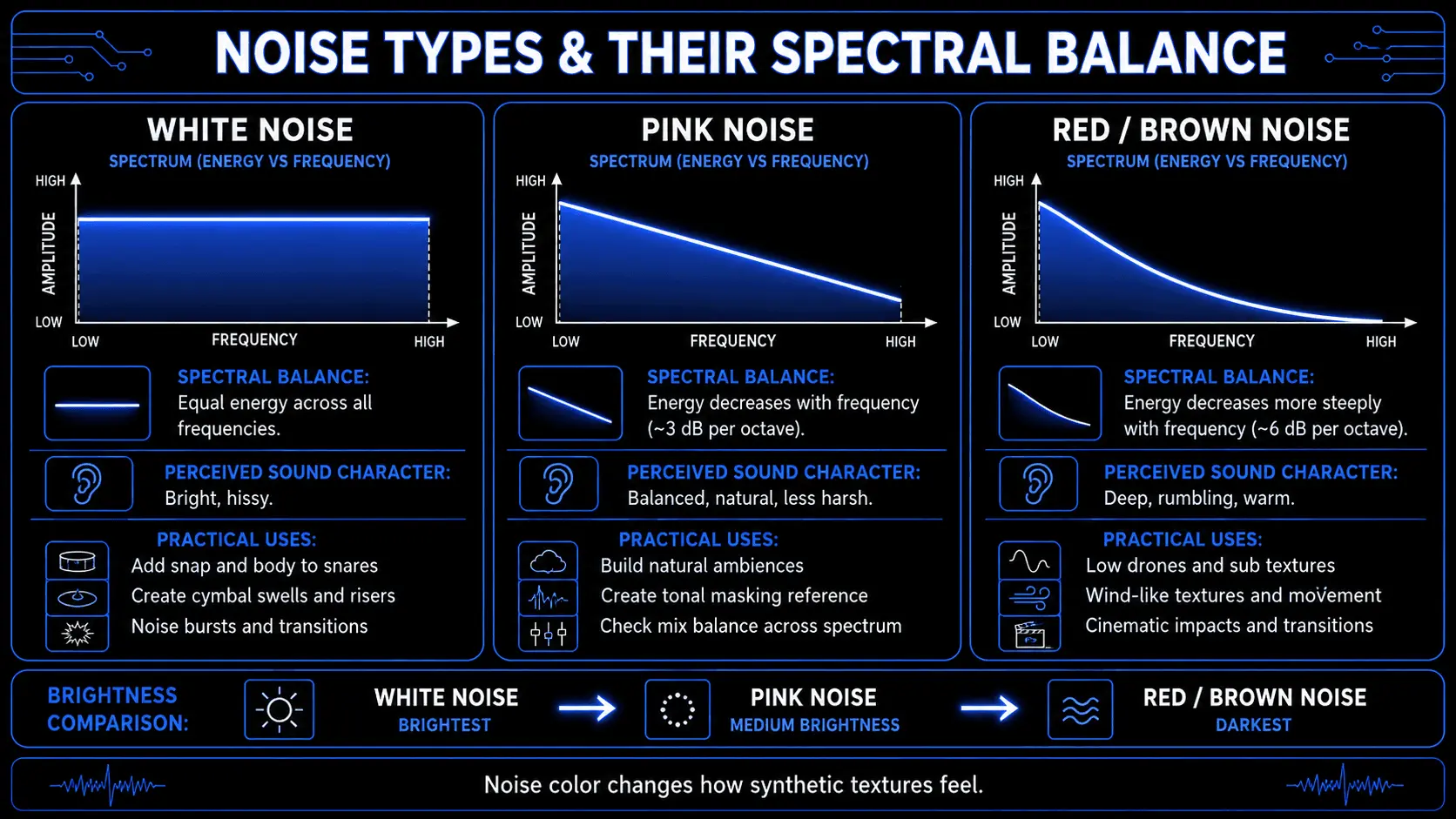
The most common variant is white noise, which contains equal energy per unit of bandwidth across the entire frequency spectrum. This results in a highly abrasive, hissing sound reminiscent of television static. In electronic music production, white noise is incredibly useful for synthesizing transient bursts like snare drums, handclaps, and dramatic cymbal rises.
By applying internal filtering directly to the noise circuit, engineers can achieve pink noise or red noise. Pink noise contains equal energy per octave, meaning the lower frequencies are accentuated while the higher frequencies step down gradually. This provides a sound that human ears perceive as much more balanced and natural, mimicking the rushing roar of a distant waterfall or heavy wind. Utilizing noise shaping techniques allows sound designers to simulate the organic acoustic irregularities found in nature, providing a crucial element of realism when blending synthetic sounds with traditional instrumentation.
Pitch Architecture, Octaves, and Intervals
Controlling the frequency output of an oscillator requires a structured pitch architecture. In analog synthesizers, this is traditionally governed by the one-volt-per-octave standard, where a change of one volt in the control signal shifts the pitch of the oscillator by precisely twelve semitones.
Instruments feature coarse tuning and fine tuning controls. Coarse tuning adjusts the base pitch in steps of entire octaves or individual semitones, allowing an oscillator to be shifted upward or downward to fit the arrangement. Fine tuning allows for microscopic adjustments, shifting the pitch by cents.
By utilizing two or more independent oscillators, a sound designer can set them to distinct intervals. Tuning one oscillator a perfect fifth or a minor third above the master oscillator allows a single key press to generate a complex chordal harmony. Furthermore, intentionally detuning two identical waveforms by a small fraction of a cent introduces a physical phenomenon known as phase beating. The two waves continuously drift in and out of alignment, creating a rich, organic thickness that counteracts the sterile, static nature of raw electronic generation.
Sculpting Frequency Content: Filter Synthesis
If the oscillator is the engine of a subtractive synthesizer, the filter is its steering wheel. Filter synthesis represents the core operational phase of this entire sound engineering methodology. Without a highly responsive, musically pleasing filter, an instrument cannot effectively execute subtractive principles.

Filter Types and Frequency Response Profiles
Synthesizers utilize several distinct filter types, each possessing a specific frequency response profile that dictates which regions of the audio spectrum are targeted for elimination and which are permitted to pass through unaffected.
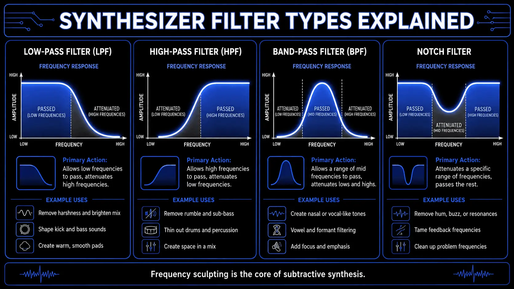
| Filter Type | Primary Action | Common Sonic Applications |
|---|---|---|
| Low-Pass (LPF) | Cuts high frequencies above the cutoff; passes lows. | Heavy basslines, warm pads, analog emulation. |
| High-Pass (HPF) | Cuts low frequencies below the cutoff; passes highs. | Thin percussion, sweeping transitions, mix cleanup. |
| Band-Pass (BPF) | Cuts highs and lows; passes a narrow center band. | Vocal formants, nasal leads, telephone speaker effects. |
| Notch (Band-Reject) | Cuts a narrow center band; passes highs and lows. | Phasing textures, complex acoustic resonances. |
The low-pass filter is the absolute standard in subtractive synthesis. Its architectural purpose is to allow low frequencies to pass through completely intact while attenuating or rolling off all frequency data above a user-defined threshold called the cutoff frequency. This filter type is foundational for transforming a bright, aggressive sawtooth wave into a warm, deep, and focus-driven tone.
Conversely, the high-pass filter executes the exact opposite function. It permits high-frequency energy to pass through cleanly while systematically eliminating low-frequency weight below the designated cutoff point. This is an essential sound design tool for stripping away unnecessary mud or sub-bass rumble from lead sounds, strings, and percussion, ensuring they sit perfectly in a dense mix without conflicting with the kick drum or bassline.
The band-pass filter combines characteristics of both low-pass and high-pass designs. It isolates a specific, narrow band of frequencies to pass through while aggressively attenuating everything below and above that center zone. The resulting sound exhibits a highly focused, nasal, or telephone-like quality, making it ideal for creating specialized mid-range accents or vocal-like vowel formants.
The notch filter, often referred to as a band-reject filter, is the inversion of a band-pass filter. It leaves the extreme highs and lows completely untouched, carving a deep, narrow hole right out of the center of the frequency spectrum. When the cutoff frequency of a notch filter is slowly moved back and forth across the spectrum, it creates a subtle, swirling phase effect that adds a sense of acoustic complexity to shifting pads and background textures.
Cutoff Frequency and Resonance Mechanics
The precise manipulation of a filter rests upon two primary parameters: the cutoff frequency and the resonance. The cutoff frequency dictates the exact point in the frequency spectrum where the filter begins its attenuation process. In a digital environment, this parameter can be pinned to an exact frequency value, while in analog synthesizers, it corresponds to a variable voltage threshold that alters the resistance of the internal circuitry.
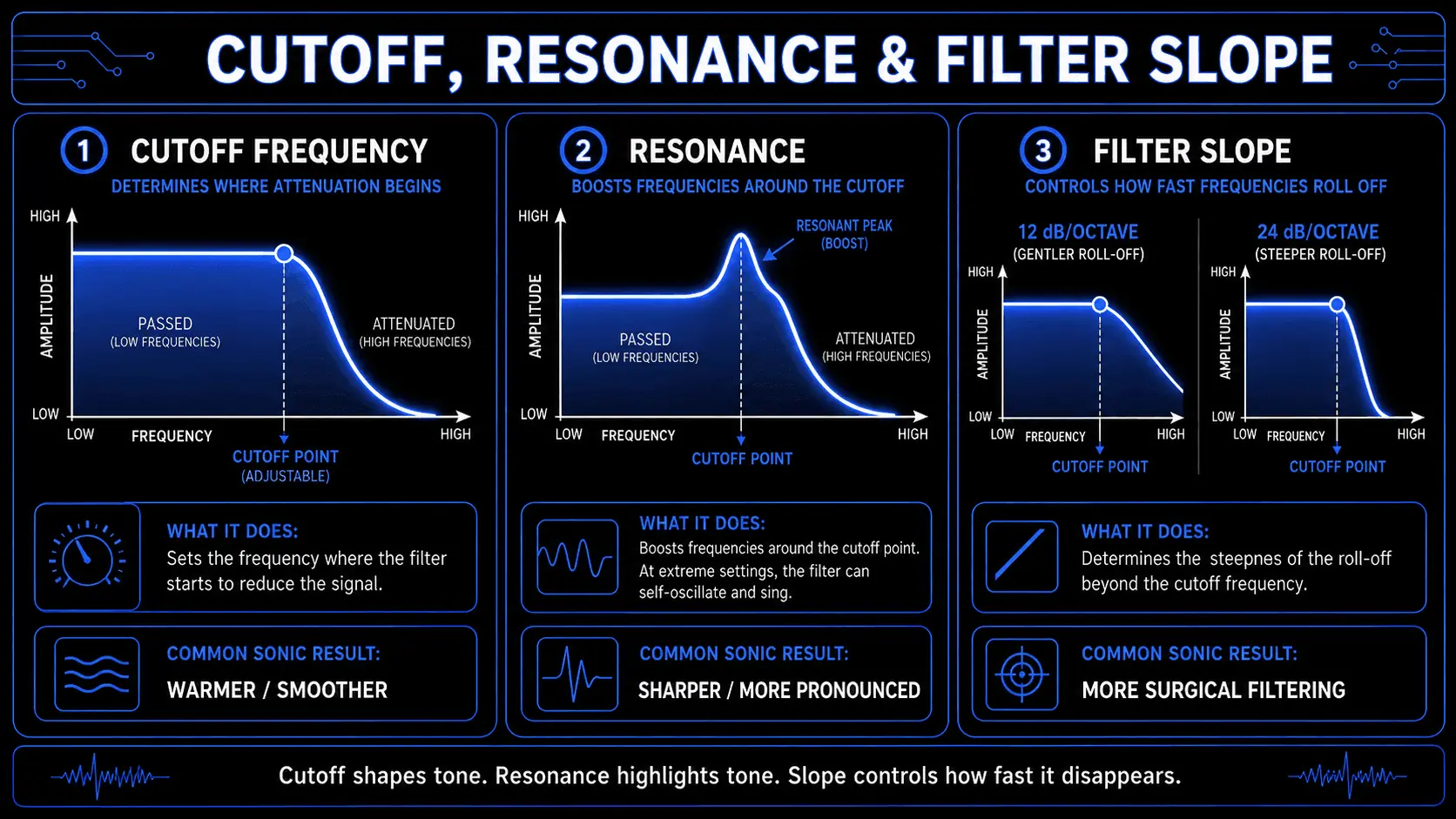
The severity with which a filter eliminates sound beyond the cutoff point is defined by its slope, measured in decibels per octave. A gentle two-pole filter offers a slope of 12dB per octave, meaning that one octave above the cutoff frequency, the volume of the signal is reduced by twelve decibels. This provides a smooth, gradual transition that sounds highly natural and acoustic. A steep four-pole filter provides a sharp slope of 24dB per octave, cutting unwanted frequencies with surgical precision. This aggressive slope is a signature characteristic of classic synthesizer sub-genres, delivering a highly focused and impactful sound.
Resonance, often labeled as emphasis or feedback, is achieved by routing a portion of the filter's output signal back into its input stage. This feedback loop creates a sharp acoustic peak or boost directly at the designated cutoff frequency. As resonance is increased, the frequencies sitting right at the cutoff threshold become significantly louder and sharper.
If the resonance control is pushed to its extreme limit, the internal feedback loop becomes so powerful that the circuit begins to oscillate entirely on its own, independent of any input from the oscillators. This phenomenon is known as self-oscillation. The filter generates a pure, piercing sine wave at the exact frequency of the cutoff point. Sound designers frequently harness this self-oscillating behavior to synthesize organic whistling sounds, sci-fi sound effects, or deep sub-bass frequencies that can be played musically across a keyboard.
Dynamic Amplitude Management: The Amplifier Section
Once an oscillator's raw signal has been generated and sculpted by the filter synthesis stage, it must pass through an amplifier to govern its overall volume across time. In hardware synthesizers, this component is known as the voltage-controlled amplifier, while software instruments refer to it simply as the amplifier or output section.
The primary function of the amplifier is to translate incoming note performance data into continuous volume scaling. When no musical notes are being played, the amplifier remains entirely closed, blocking any signal from reaching the audio outputs. When a keyboard key is pressed, an electronic command maps to the amplifier, prompting it to open and allow the sound to flow into the sound engineering environment.
Proper gain staging within the amplifier section is critical. If the collective signals from multiple oscillators overpower the internal headroom of the amplifier stage, unwanted distortion can occur. While intentional saturation can add desirable warmth, accidental digital clipping results in harsh, unmusical transients that ruin the clarity of a mix. Therefore, the amplifier section must be managed carefully, balancing internal volume controls against the master output stage of the electronic music production system.
Modulation Architecture: Envelopes
A sound that remains perfectly static in timbre and volume from the moment a key is pressed until it is released sounds artificial and fatiguing to the human ear. To inject natural expression into a patch, sound engineering utilizes modulation sources. The most critical tool for shaping a sound's contour over time is the envelope generator.
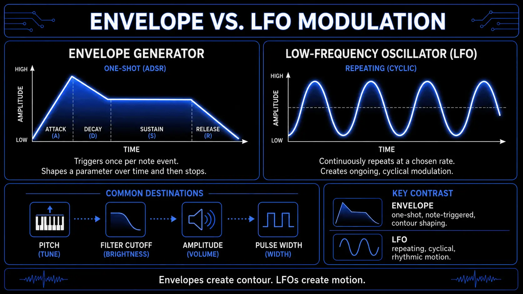
An envelope generator produces a one-shot control signal that triggers every time a new note event is received. This signal acts as an automated hand, physically adjusting a specific parameter on the user's behalf.
The Four-Stage ADSR Envelope
The standard layout for a synthesizer envelope generator consists of four distinct, sequential stages: Attack, Decay, Sustain, and Release.
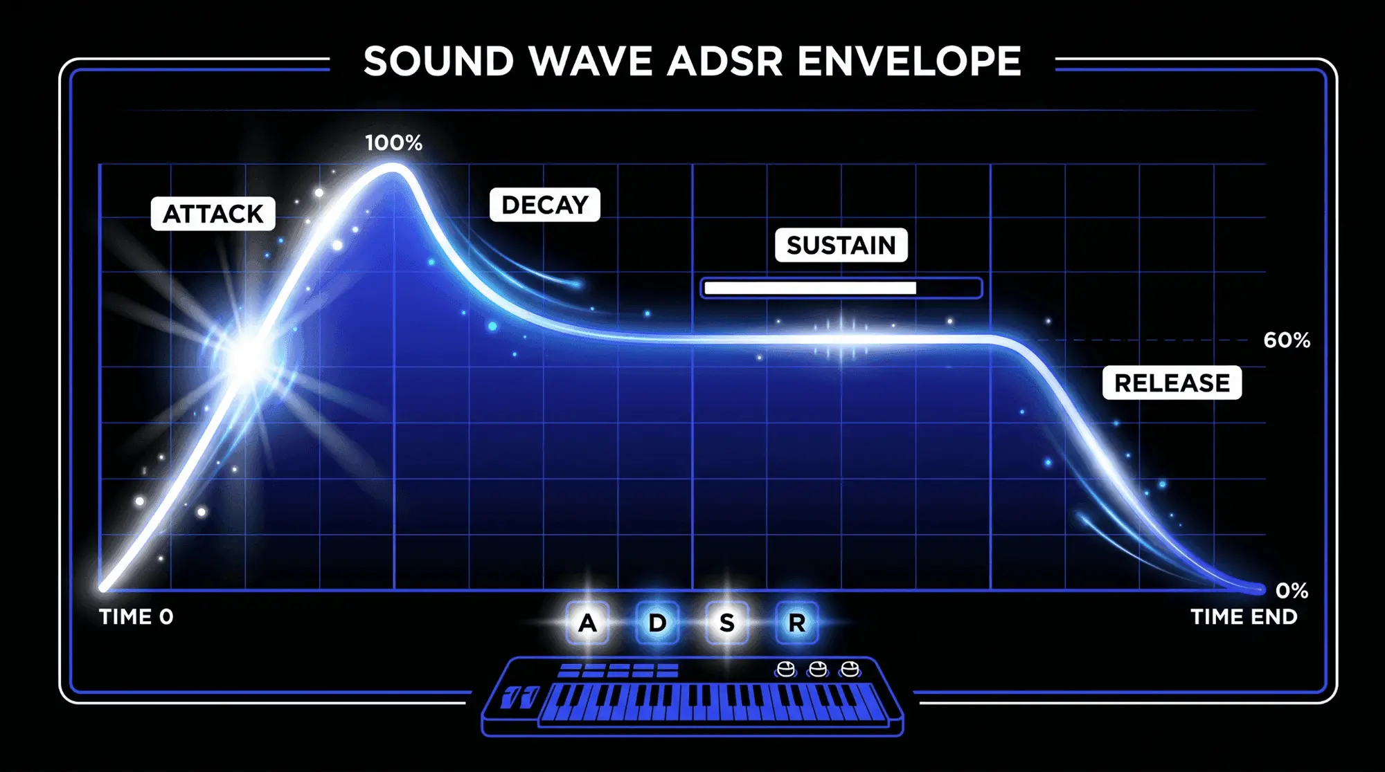
- Attack determines the exact duration of time it takes for the envelope's control signal to rise from zero to its absolute peak value once a note is struck. A setting of zero milliseconds creates an instantaneous transition, producing a sharp, clicky attack ideal for percussion and aggressive basslines. Conversely, an extended attack time causes the sound to fade in gradually, a requirement for creating slowly evolving ambient string textures.
- Decay defines the amount of time the signal takes to fall from its peak value down to the designated sustain level. If the sustain level is set to maximum, the decay stage becomes irrelevant, as the sound will simply remain at its peak volume. However, when crafting plucky or percussive sounds, a short decay time is essential to pull the signal down rapidly, creating a sense of natural acoustic decay.
- Sustain represents the only parameter in the ADSR chain that measures volume or value rather than time. It dictates the constant level at which the control signal rests for as long as the musical note continues to be held down by the performer. For sustained organ sounds or driving lead notes, the sustain should be set high. For sharp, fleeting sounds like acoustic plucks, the sustain should be pulled down to zero.
- Release establishes the time it takes for the control signal to drop from its current sustain level all the way back down to absolute zero once the user lets go of the note. A short release time causes the sound to cut off immediately, while a long release time allows the sound to trail off smoothly over several seconds, filling the ambient space of a production.
Amplitude Envelope Mapping
When an envelope generator is mapped directly to the voltage-controlled amplifier, it is called the amplitude envelope. This layout controls the physical lifecycle of the sound's volume.
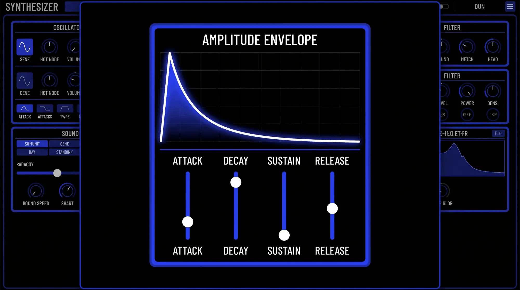
For instance, when synthesizing a percussive sound like a woodblock, the amplitude envelope requires a zero-millisecond attack, a rapid decay of roughly two hundred milliseconds, a sustain level of absolute zero, and a very short release. This ensures that the moment a key is struck, the sound bursts forth at maximum volume and instantly dies away, regardless of how long the performer holds the key down.
For an ambient pad, the envelope is configured with a two-second attack, a three-second decay, a high sustain level around eighty percent, and a three-second release, allowing notes to seamlessly morph into one another.
Filter Envelope Mapping
Mapping a dedicated envelope generator to the filter cutoff frequency is one of the most effective sound design techniques in subtractive synthesis, known as filter modulation. When applied, the filter cutoff frequency actively moves along the timeline based on the shape of the ADSR curve.
An intensity control, often labeled as envelope amount or modulation depth, dictates how far the filter cutoff is pushed from its baseline setting. If the envelope amount is set to a high positive value, the filter cutoff will tear open during the attack stage, brightening the sound rapidly, before closing back down during the decay and sustain stages. This creates a highly dynamic timbre that mimics the natural behavior of brass instruments, which burst with high-frequency harmonics the moment they are blown and quickly mellow out as the note is sustained.
Pitch Envelope Mapping
When an envelope is routed directly to the pitch controls of the primary oscillators, it allows for automatic frequency slides over time. Pitch envelope mapping must be executed with extreme restraint, as a massive pitch sweep can quickly sound chaotic and unmusical.
However, a very fast pitch envelope is crucial for synthesizing the initial click or snap of a punchy electronic kick drum or bass patch. By configuring the pitch envelope with a fast attack and an incredibly short decay time, and setting the modulation depth to a high positive value, the oscillator will execute a lightning-fast downward pitch sweep at the absolute beginning of the note event. The human brain perceives this microscopic frequency drop not as a sliding pitch, but as a tight, organic physical impact, giving the sound an immediate punch that cuts through dense loudspeakers.
Modulation Architecture: Low-Frequency Oscillators
While an envelope generator executes a single, one-shot control cycle per note event, a low-frequency oscillator provides continuous, repeating modulation. Operating far below the range of human hearing—typically between 0.1 Hz and 20 Hz—an LFO does not generate audible audio signals. Instead, it acts as a rhythmic cyclical driver for other target parameters within the synthesizer architecture.
Pitch Modulation Dynamics
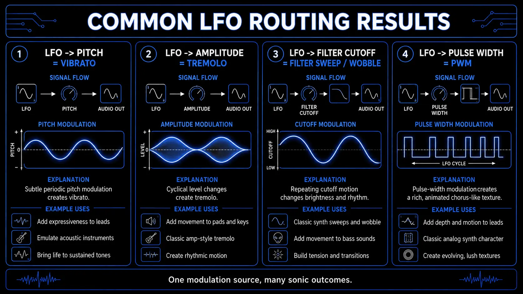
Routing an LFO to modulate the master pitch of the audio oscillators results in a periodic frequency deviation above and below the baseline pitch. When executed at a moderate speed of roughly 5 to 7 Hz with a subtle modulation depth, this technique synthesizes a natural musical vibrato. This mimics the organic pitch instability of a human vocalist or a string player gently rocking their finger on a fretboard, instantly humanizing an otherwise rigid electronic signal.
If the LFO speed is accelerated up into the audible range—above 20 Hz—the pitch modulation happens so rapidly that the human ear can no longer distinguish individual cycles. Instead, the process shifts into basic frequency modulation, generating brand-new, complex sideband harmonics that give the sound a metallic, bell-like, or industrial texture.
Pulse-Width Modulation Mechanics
When a square or pulse wave is selected as the primary sound source, an LFO can be mapped to modulate its pulse width. This specific technique is known as pulse-width modulation.
As the LFO moves through its cycle, it smoothly alters the duty cycle of the pulse wave back and forth between a wide, open geometry and a narrow, nasal shape. Tonal analysis reveals that this continuous shifting causes the internal harmonic overtones to constantly phase cancel and reinforce one another. Acoustically, this creates a rich, swirling, chorus-like texture that makes a single oscillator sound like a massive wall of multiple detuned instruments. Pulse-width modulation is a staple sound design technique for engineering lush, vintage analog string pads and thick lead lines without consuming additional oscillator voices.
Filter Cutoff Modulation Dynamics
Mapping a low-frequency oscillator to the cutoff frequency of a low-pass or high-pass filter creates a rhythmic variation in the overall brightness of the sound. If the LFO is configured with a slow rate, it generates a gentle, sweeping motion that makes pads and textures feel alive and constantly shifting over several musical bars.
In modern electronic music production, accelerating the LFO rate and syncing its speed directly to the master tempo of the host digital audio workstation allows for highly rhythmic filtering. This technique is the driving force behind the iconic wobble bass styles found in various bass music sub-genres, where the filter snaps open and shut precisely on the musical beat or subdivision, turning a sustained sub-bass tone into an infectious rhythmic element.
Amplitude Modulation Dynamics
When an LFO is routed to control the volume level of the voltage-controlled amplifier, it creates a periodic fluctuation in volume known as amplitude modulation or musical tremolo. This introduces a fluttering quality to pads and lead lines.
By utilizing different LFO waveform shapes, the characteristics of this volume fluctuation can be altered dramatically. A sine wave LFO provides a smooth, gentle volume rise and fall, whereas a square wave LFO acts as a hard gate, snapping the volume instantly between maximum and absolute silence. This creates a stuttering effect that can turn a simple wall of sound into an interlocking rhythmic pattern that syncs perfectly with a track's percussion.
Practical Applications in Sound Design and Electronic Music Production
To effectively harness the power of a subtractive instrument, a producer must move away from theoretical architecture and look at practical sound design techniques. Subtractive synthesis is incredibly versatile, capable of engineering distinct textures across multiple musical genres.

Engineering Deep and Thick Basslines
Crafting a powerful bassline that anchors the low end of a club track requires precise control over harmonic density and transient impact.
- Oscillator Selection: Begin by activating two oscillators in the mixer section. Set Oscillator 1 to a high-energy sawtooth wave to provide an abundance of upper-frequency grit. Set Oscillator 2 to a square wave, which introduces a hollow midrange character. Shift the coarse tuning of Oscillator 2 downward by exactly one full octave relative to Oscillator 1 to establish a dense low-end foundation.
- Detuning: To introduce warmth and physical weight, adjust the fine-tuning of Oscillator 2 upward by roughly 5 to 8 cents, leaving Oscillator 1 locked at the center pitch. This slight deviation creates a slow phase drift that thickens the combined waveform.
- Filter Shaping: Route the combined signal into a steep 24dB per octave low-pass filter. Pull the cutoff frequency down significantly, sitting around 150 Hz, to completely eliminate the harsh, buzzing highs. Introduce a small amount of resonance—roughly fifteen percent—to add a clear point of definition right at the cutoff threshold.
- Envelope Modulation: Map a dedicated envelope generator to the filter cutoff frequency with a high modulation depth. Configure the envelope with an immediate zero-millisecond attack, a tight decay of three hundred milliseconds, a low sustain level around ten percent, and a short release matching the decay. This creates a classic plucky bass sound, where the filter rips open instantly on the transient hit to deliver a sharp punch before snapping shut to leave only a clean, warm sub-bass hum.
Designing Sharp and Punchy Lead Voices
An effective lead sound must cut through a dense wall of drums and vocals, asserting itself as the melodic centerpiece of a composition.
- Oscillator Sync: Select two sawtooth waves across both primary oscillators. To achieve maximum bite, activate the oscillator sync function. This locks the phase cycle of Oscillator 2 to the master cycle of Oscillator 1. Whenever Oscillator 1 completes a full wave, it forces Oscillator 2 to reset instantly, creating sharp, jagged angles in the resulting waveform that yield aggressive, piercing harmonics.
- Filter Emphasis: Route this synced signal into a high-pass filter with a cutoff frequency set around 200 Hz to strip away any low-end weight that might muddy up the master mix. Next, run the remaining signal into a 12dB per octave low-pass filter. Push the resonance control up to roughly seventy percent, just below the point of self-oscillation. This emphasizes the mid-range frequencies, giving the lead an intense, vocal-like edge.
- Modulation Mapping: Assign a pitch envelope to Oscillator 2 with a fast attack and a moderate decay time. As the envelope triggers, it slides the pitch of the synced oscillator downward rapidly, causing the synchronized harmonics to sweep violently through the midrange. This results in a biting, aggressive lead sound that commands attention. Finally, map a subtle LFO to the pitch of both oscillators to introduce a gentle vibrato when notes are held down, preventing the melody from sounding rigid.
Constructing Ethereal and Lo-Fi Pads
Ambient pads require a completely inverted sound design philosophy, prioritizing slow evolution, spatial width, and a soft, vintage character.
- Oscillator Blending: Activate three independent oscillators. Set Oscillator 1 to a smooth triangle wave to provide a warm fundamental root. Set Oscillator 2 and Oscillator 3 to identical pulse waves. Spread them wide across the stereo field using your synthesizer's panning matrix.
- Pulse-Width Modulation: Map an LFO running a slow sine wave at 0.5 Hz to modulate the pulse width of both Oscillator 2 and Oscillator 3. Invert the modulation phase on the third oscillator so that as one wave widens, the other narrows. This creates a constantly shifting harmonic landscape that delivers incredible spatial depth.
- Filter and Envelope Architecture: Route this blend into a gentle 12dB per octave low-pass filter with the cutoff pulled down to a dark, subdued setting around 500 Hz. Configure the amplitude envelope with an extended attack time of two full seconds and a long release time of three seconds. This ensures that notes fade into existence smoothly and hang in the air long after the keys are released, blending chords together into a seamless atmospheric texture.
- Lo-Fi Enhancements: To add a distinct lo-fi texture, introduce a small amount of white noise via the mixer section and apply noise shaping to dull its upper frequencies. Map a random sample-and-hold LFO to subtly modulate the fine tuning of all oscillators, mimicking the unpredictable pitch drift of an aging, unserviced analog tape machine.
Synthesizing Experimental Drum Timbres
A subtractive instrument is not limited to harmonic melodies; it can be transformed into a highly capable electronic drum machine by exploiting its noise sources and fast modulation paths.
To synthesize a punchy, electronic kick drum, select a single oscillator generating a pure sine wave. Bypass the main filter section entirely to preserve maximum low-end energy. Configure the amplitude envelope with a zero-millisecond attack and a rapid decay of roughly one hundred and fifty milliseconds with a sustain level of absolute zero.
Next, map a dedicated pitch envelope to the oscillator with a modulation depth set extremely high. Set its decay time incredibly short, around twenty milliseconds. This forces the sine wave to execute a violent downward frequency drop at the start of the note, creating a tight, organic physical impact that simulates a heavy acoustic beater striking a drum head.
To engineer a synthetic snare drum or handclap, deactivate the standard geometric oscillators entirely and turn the white noise generator up to maximum volume. Route this abrasive hiss into a band-pass filter centered firmly in the mid-range around 1 kHz to isolate the body of the drum.
Configure the filter envelope with a sharp attack and a moderate decay of three hundred milliseconds. This allows the noise to burst forward with a sharp snap and quickly fade away. Layering a subtle triangle wave tuned to a fundamental frequency of 150 Hz beneath this noise burst provides a solid low-mid thump, simulating the physical resonance of a snare drum's wooden shell.
Using ACE Studio as Source Material for Subtractive Sound Design
Subtractive synthesis usually begins with sawtooth, square, pulse, or noise waveforms, but an oscillator is not the only possible source. Any recording with enough harmonic information can be filtered, enveloped, layered, and resampled using the same principles.
This opens an interesting role for ACE Studio. Instead of treating it only as a vocal production tool, producers can use it to create expressive instrument performances and complementary audio layers, then process those sounds as raw material inside a subtractive sound design chain.
Turn MIDI Into Expressive Instrument Layers
A traditional subtractive patch interprets MIDI through oscillators, envelopes, and modulation. The same MIDI phrase can also control an AI instrument in ACE Studio, creating a performed layer with natural articulation, dynamics, and movement.
ACE Studio’s AI Instruments generate performances from MIDI and include editing tools for notes, articulations, expression, and ensembles. Current instrument options include strings, saxophone, trumpet, and duduk.
This becomes useful when a synthesized part has the correct notes and tone but still feels too geometrically consistent.
The patch may already sound powerful, but you could send the same MIDI line to a cello or other bowed AI instrument. Once generated, remove most of that layer’s low end, soften its upper frequencies, and keep only the bow attack and shifting midrange.
The synthesizer continues to provide weight and stability. The filtered instrument layer contributes small variations in tension, timing, and articulation. The result is not an orchestral part placed over a bass patch. It is a single hybrid sound whose electronic and performed elements have been deliberately sculpted.
Generate One Layer, Then Carve It Into Shape
ACE Studio’s Add a Layer tool can analyze a selected part of a project and generate a new audio layer according to the chosen type and a short description. The producer defines the time range, layer category, style, and, when relevant, the instrument.
For subtractive synthesis, the most productive approach is not to keep every generated layer unchanged. Use the result as dense source material and remove most of it.
Suppose an ambient pad sounds wide but lacks movement in the center of the stereo image. Select four or eight bars and request one restrained layer, such as:
Soft bowed texture, low movement, muted attack, no percussion
Once the layer has been generated:
- Apply a high-pass filter to remove frequencies competing with the bass.
- Apply a low-pass filter to reduce brittle detail.
- Shorten or reshape the amplitude envelope.
- Automate the cutoff so the layer appears only during selected phrases.
- Resample the processed layer with the original pad.
This is still subtractive sound design. ACE Studio supplies a performance-shaped source, while the filter determines what listeners actually hear.
The same technique can add texture to percussion. A short generated scrape, impact, breath-like noise, or tonal effect can be filtered into a transient and layered beneath a synthesized snare. The advantage is specificity. You begin with material related to the musical moment, then reduce it to the narrow function the arrangement needs.
For larger textures, ACE Studio’s instrument Unison Mode can combine multiple AI instruments on one instrument track. That combined performance can then be filtered and resampled as a single layer rather than managed as several unrelated parts.
The purpose is not to replace oscillator programming. A sawtooth remains useful because its harmonic structure is predictable, and a pulse wave remains useful because its width can be modulated with precision. ACE Studio provides a different kind of starting point – one shaped by articulation, breath, bow movement, and performance dynamics.
Advanced Subtractive Synthesis Techniques
Once a producer has mastered basic oscillator mixing and standard filter synthesis, they can begin exploring advanced subtractive synthesis techniques to push the boundaries of modern electronic music production.
Waveform Manipulation and Waveform Shaping
Advanced instruments provide specialized tools for altering raw geometric shapes prior to the filter stage, a process widely known as waveform shaping. Beyond standard pulse-width modulation, many modern synthesizers feature a wavefolding engine.
Wavefolding operates by taking an audio signal that exceeds a specific clipping threshold and, instead of squaring it off into digital distortion, physically flipping the peak of the waveform backward into itself. This introduces highly complex, non-linear odd harmonics that turn a simple triangle wave into a metallic, complex texture. By automating the wavefolding depth with an envelope or LFO, a sound designer can achieve intense tonal movement that responds dynamically to performance intensity.
Complex Signal Routing and Modular Synthesis
For decades, hardware sound engineering was confined to fixed signal paths. The advent of modular synthesis exploded these limitations by treating every single component of a synthesizer as an independent, isolated unit that must be manually connected using physical patch cables.
Modern software synthesizers recreate this workflow via internal digital modulation matrices. Advanced routing allows for cross-modulation, where the output of an audible audio oscillator is routed to modulate the filter cutoff frequency of another channel. This audio-rate modulation happens so rapidly that it bypasses standard rhythmic movement, introducing gritty, complex sidebands and screaming timbral distortions that add immense character to aggressive industrial tracks and futuristic sound design.
Multi-Layering Workflows and Unison Engine Optimization
When a sound design project requires a massive, larger-than-life presence, simple two-oscillator patches can fall short. This is where multi-layering workflows and the optimization of a synthesizer's unison engine become vital.
The unison engine operates by duplicating a single note performance across multiple hidden voices simultaneously. For instance, activating an eight-voice unison engine on a basic sawtooth patch immediately generates eight identical waveforms the moment a single key is pressed. By utilizing a detune control, the producer can spread the pitch of these eight voices apart by a user-defined margin, while a stereo spread control pans the detuned voices across the stereo field. This creates a dense wall of sound that sounds incredibly wide, thick, and powerful, serving as the core foundation for modern pop hooks and cinematic electronic scores.
Ring Modulation and Cross-Modulation Routing
Ring modulation is an advanced audio synthesis technique that multiplies two distinct audio signals together in real time. The mathematical output of this multiplication contains the sum and the difference of all the frequencies present in both source signals, while completely eliminating the original fundamental frequencies themselves.
If Oscillator 1 is generating a sawtooth wave at 100 Hz and Oscillator 2 is generating a sine wave at 300 Hz, a ring modulator will output an independent signal containing complex, non-harmonic frequencies at 400 Hz and 200 Hz. The acoustic result is distinctly metallic, dissonant, and bell-like. By subtly blending a ring-modulated signal back into a standard subtractive patch, an engineer can introduce an industrial grit and mechanical complexity that works exceptionally well for eerie cinematic scores, robotic sound effects, and experimental electronic music production.
Technical Troubleshooting: Common Challenges and Engineering Solutions
When working extensively with subtractive instruments, sound designers frequently encounter technical hurdles that can degrade the quality of a mix. Understanding the engineering solutions to these common challenges is an essential skill.
Eliminating Low-End Mud and Frequency Masking
A frequent issue in electronic music production occurs when multiple subtractive patches retain unnecessary low-frequency energy. If a lush lead line, a stereo pad, and a synthesized snare drum all contain harmonic data down below 200 Hz, these signals will conflict with the main kick drum and bassline. This results in a muddy, indistinct mix known as frequency masking.
The solution lies in aggressive filter synthesis management. Every patch that does not serve as a primary bass element should be routed through a high-pass filter. By setting the cutoff frequency between 100 Hz and 250 Hz and utilizing a gentle 12dB per octave slope, you can strip away the useless low-end rumble while leaving the crucial mid-range and high-frequency character completely untouched, opening up immense clarity within the mix.
Remedying Static and Lifeless Patches
If a synth patch sounds boring and fails to hold a listener's attention, the underlying cause is almost always a lack of modulation. A patch that features fixed oscillator volumes and a completely static filter cutoff sounds artificial and uninspiring.
To breathe life into a static patch, introduce subtle layers of modulation across multiple targets. Map a slow LFO to gently move the filter cutoff frequency by just a few degrees. Next, activate pulse-width modulation on your square waves to create an organic chorus effect. Finally, map velocity control within your synthesizer's modulation matrix so that playing a key harder automatically increases the filter envelope depth and shortens the attack time. This ensures that the instrument responds dynamically to human performance, mimicking the organic variations of an acoustic instrument.
Managing Analog Tuning Drift
Producers working with vintage hardware instruments face a unique physical challenge: analog tuning drift. Unlike digital oscillators that calculate pitch mathematically, voltage-controlled analog oscillators rely on physical capacitors and transistors. These components are highly sensitive to environmental temperature fluctuations. When an instrument is first powered on, its internal circuitry is cold, causing the pitch to drift sharp or flat.
To remedy tuning drift, always allow your hardware synthesizers to sit powered on for at least fifteen to thirty minutes to reach a stable internal operating temperature before attempting to record or calibrate them. Additionally, utilize the instrument's master fine-tuning control alongside a dedicated digital tuner utility within your DAW to ensure the oscillators remain perfectly centered. If a dual-oscillator patch drifts too far apart, it can transition from a pleasing warmth to an unpleasant dissonance, requiring careful realignment.
Integration Strategies for Modern Electronic Music Production Workflows
Integrating subtractive synthesizers smoothly into a modern digital studio environment requires a balance between creative freedom and systematic organization. Whether utilizing hardware instruments or software plugins, following a structured workflow maximizes production efficiency.

When building a track within a DAW like Ableton Live, Logic Pro, or FL Studio, it is highly beneficial to separate the sound design phase from the mixing phase. When inspiration strikes, focus entirely on the core parameters of your subtractive patch—selecting the correct oscillator types, setting your filter types, and dialing in your ADSR envelopes.
To preserve CPU processing power and lock in your creative decisions, utilize your DAW's freeze and flatten or bounce-in-place utilities. Converting a heavy software instrument track into a static audio file provides several advantages: it prevents accidental parameter shifts, frees up system resources, and opens up new opportunities for creative audio editing, such as reversing reverb tails or chopping up transients.
Furthermore, consider routing your subtractive synths into dedicated external effects chains. While built-in synthesizer effects are convenient, processing your patch through high-quality third-party distortion, lush algorithmic reverbs, and stereo delays allows the sound to blend naturally into the acoustic space of your production, elevating your tracks to a professional standard.
Frequently Asked Questions
What makes subtractive synthesis different from additive synthesis?
Subtractive synthesis begins with a harmonically rich waveform and uses filters to remove unwanted frequencies. Additive synthesis starts from silence and builds a complex sound by layering pure sine waves together.
Why are low-pass filters used more than other filter types?
Low-pass filters closely mimic how sound behaves in the physical world. In nature, high frequencies are easily absorbed by walls, air, and distance, making a low-pass filter sound highly natural to human ears.
What is the purpose of pulse-width modulation?
Pulse-width modulation uses an LFO to continuously shift the shape of a square wave, creating a rich, swirling chorus effect that adds immense thickness to a patch without using extra oscillators.
Can I create a sub-bass sound using a subtractive filter?
Yes. You can achieve this by taking a rich sawtooth or square wave and pulling a low-pass filter cutoff frequency down below 80 Hz, or by using a pure sine wave oscillator with the filter completely bypassed.
What does the resonance control actually do to the sound?
Resonance takes a portion of the filter's output signal and routes it back into the input, creating a sharp volume boost directly at the cutoff frequency that sharpens the sound.
What is the difference between an envelope and an LFO?
An envelope is a one-shot modulator that triggers once per note event and runs through its ADSR stages. An LFO is a continuous, cycling modulator that repeats its waveform indefinitely at a set speed.