Microphone Polar Patterns: The Simple Guide to Better Sound Capture
Key Takeaways
- Microphone polar patterns control what a microphone hears and rejects, so choosing the right pattern shapes the recording before mixing or editing begins.
- Cardioid, supercardioid, hypercardioid, omnidirectional, figure-eight, wide cardioid, and shotgun patterns all solve different recording problems, from vocal isolation to room capture and outdoor dialogue.
- Null points, acceptance angles, distance factor, and off-axis rejection help engineers place microphones more precisely instead of relying on guesswork.
- Proximity effect and off-axis coloration change depending on the polar pattern, which is why the same source can sound fuller, thinner, cleaner, or muddier with different mic choices.
- ACE Studio cannot change a polar pattern after recording, but it can help turn a limited take into editable musical material through Vocal to MIDI, AI vocals, choir parts, instruments, stem separation, and video-based sound creation.
Understanding how microphone polar patterns shape sound capture
Selecting the correct microphone tool requires a comprehensive understanding of transducer mechanics, acoustic environments, and directional characteristics. This guide provides an exhaustive analysis of microphone polar patterns, detailing the underlying engineering physics, technical specifications, and strategic production workflows required to capture pristine audio in any scenario.
Technical Foundations of Sound Pickup and Directionality
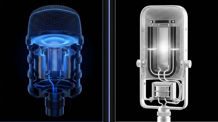
At the core of audio engineering is the concept of acoustic transduction: converting mechanical acoustic energy into an equivalent electrical voltage. How a microphone handles sound pickup from different directions is determined by its mechanical capsule architecture and acoustic housing design.
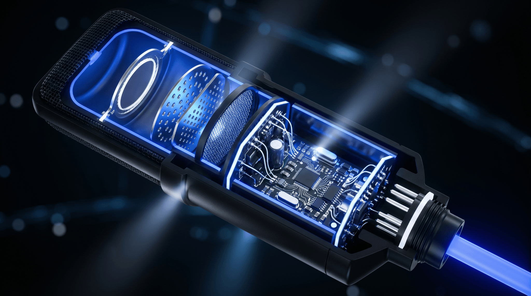
Every microphone capsule contains a microscopic diaphragm that reacts to changes in sound pressure level. The specific directionality of the transducer depends on whether the capsule is built as a pressure-operated system or a pressure-gradient system.
Pressure-Operated Transducers
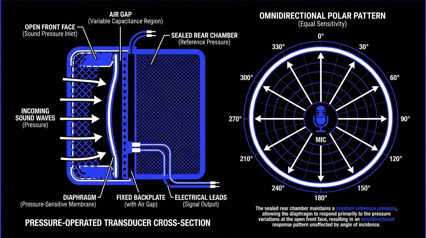
In a pressure-operated configuration, the rear side of the diaphragm is completely sealed within a fixed, airtight chamber. The diaphragm reacts exclusively to the fluctuating air pressure on its exposed front face, regardless of the angle from which the sound wave arrives. Because sound pressure is a scalar quantity rather than a vector quantity, these capsules exhibit an omnidirectional pattern. They capture sound uniformly across a full 360-degree sphere.
Pressure-Gradient Transducers
In a pressure-gradient system, the diaphragm is exposed to the open air on both its front and rear faces. The mechanical movement of the diaphragm is driven entirely by the instantaneous difference in sound pressure between the front and back surfaces.
Sound waves arriving from the side strike both faces of the diaphragm at exactly the same time and with identical force, causing the forces to cancel out and resulting in zero diaphragm movement. This fundamental physics principle creates a bidirectional pattern, also known as a figure-eight pattern.
Acoustic Delay Networks and Labyrinths
To engineer directional microphones that fall between completely omnidirectional and fully bidirectional, manufacturers use acoustic delay networks. By cutting precise rear ports, slots, and labyrinths into the microphone housing, sound waves hitting the back of the microphone are routed through an internal path before reaching the rear side of the diaphragm.
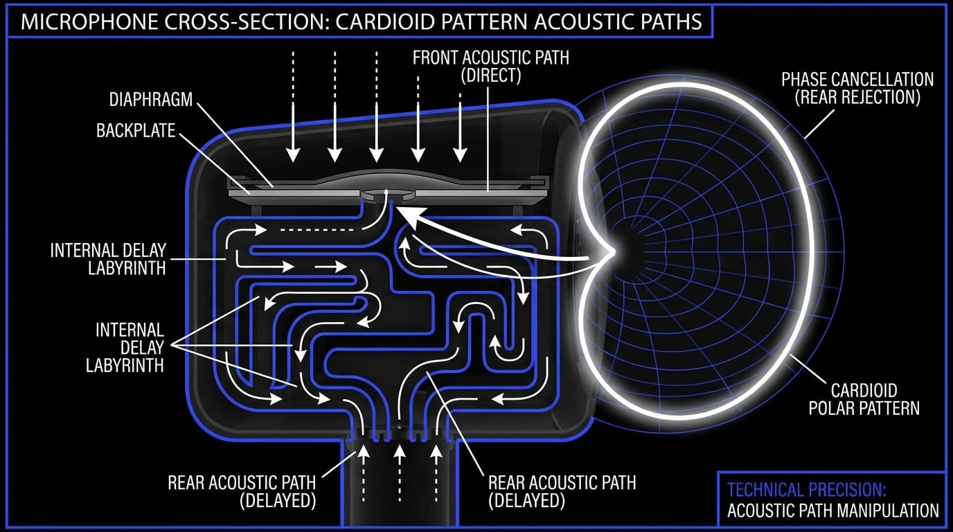
This acoustic path delays the sound wave by an exact amount of time. When a sound wave arrives from 180 degrees off-axis, the internal delay causes it to strike the rear face of the diaphragm in perfect synchronization with the external wave striking the front face.
Because the two forces are equal and opposite, they cancel each other out entirely, creating a zone of total silence known as a null point at the rear of the microphone. This clever combination of pressure and pressure-gradient principles forms the foundation of the cardioid pattern.
Understanding the Decibel Scale in Audio Engineering

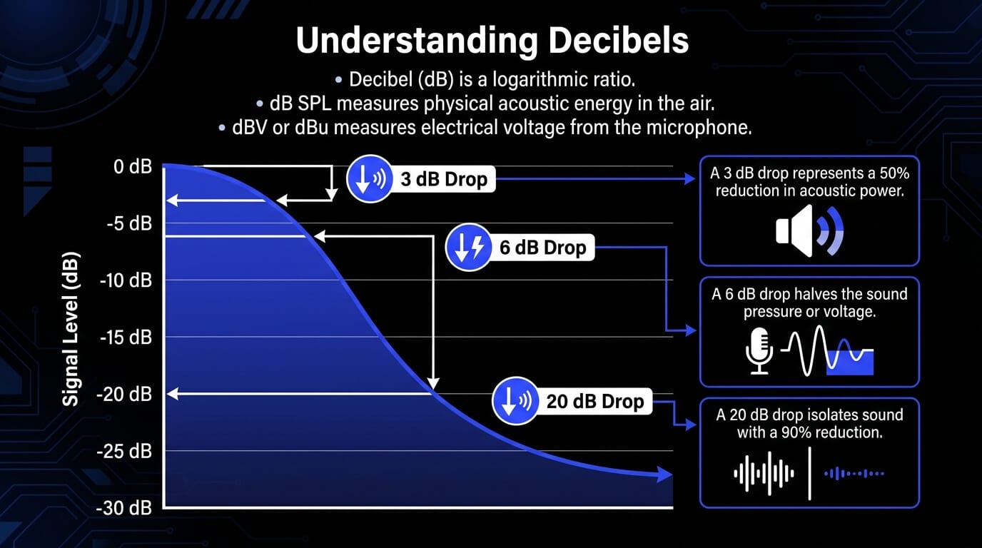
To accurately read polar diagrams and analyze microphone sensitivity, you must understand the decibel scale. The decibel, abbreviated as dB, is not an absolute measurement of physical weight or distance. Instead, it is a logarithmic ratio used to compare two distinct values of electrical voltage or acoustic sound pressure.
Because human hearing is highly nonlinear, our perception of loudness scales logarithmically rather than linearly. A linear scale would require unmanageably large numbers to express the vast range between the quietest sound a human can detect and the roar of a jet engine. The logarithmic decibel scale compresses this massive range into a practical 0 to 140 dB span.
When dealing with acoustic sound pressure or electrical voltage inside a microphone, the decibel formula is expressed as follows:
dB = 20 * log10 (P1 / P2)
In this equation, P1 represents the measured sound pressure or voltage level, and P2 represents a standardized reference point.
Sound Pressure Level versus Electrical Volts
In audio engineering, the decibel scale shifts depending on whether you are measuring acoustic waves in the air or electrical signals in a cable:
- dB SPL (Sound Pressure Level): Measures physical acoustic energy in the air, using a baseline reference point of 20 micropascals, which represents the threshold of human hearing.
- dBV or dBu: Measures the electrical voltage produced by the microphone capsule. For example, dBV uses a reference level of 1 Volt RMS. Because microphones output tiny signals, their sensitivity ratings are typically written as a negative number, such as -40 dBV per Pascal.
The Significance of Decibel Changes in Polar Dynamics
When evaluating a microphone pickup chart, decibel values indicate how much a signal drops when a sound source moves away from the front of the capsule.
Because the scale is logarithmic, these value drops represent significant changes in signal strength:
- A drop of 3 dB represents a 50 percent reduction in acoustic power. On a polar chart, the angle where the signal drops by 3 dB defines the boundary of the primary usable pickup zone.
- A drop of 6 dB represents a 50 percent reduction in sound pressure amplitude or voltage. This means the microphone signal voltage is cut exactly in half.
- A drop of 20 dB represents a 90 percent reduction in sound pressure amplitude. Any sound entering the microphone at an angle with 20 dB of attenuation is effectively isolated from the main recording.
How to Deconstruct a Polar Pattern Diagram
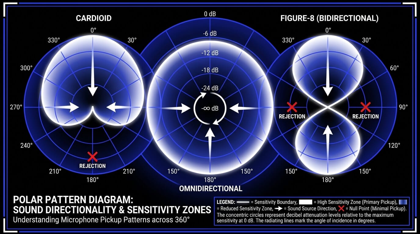
A polar pattern diagram is a two-dimensional circular graph that maps a microphone three-dimensional sensitivity across a 360-degree space. Understanding how to read these charts is essential for predicting how a microphone will behave in real-world acoustic environments.
The Circular Coordinates and Axes
The circular graph represents a top-down view of the microphone capsule:
- The 0-degree mark is located at the absolute top of the chart. This represents the primary on-axis direction, pointing directly at the front of the microphone capsule.
- The 180-degree mark is located at the bottom of the chart. This represents the rear axis, pointing directly at the back of the microphone.
- The 90-degree and 270-degree marks represent the exact left and right sides of the microphone capsule.
Interpreting Concentric Attenuation Rings
The grid lines running around the chart consist of concentric circles that expand outward from the center point. The outermost circle represents the maximum sensitivity of the microphone, designated as 0 dB. Each inner circle represents a progressive drop in sensitivity, usually marked in steps of 5 dB or 10 dB.
To find the sensitivity at a specific angle, follow the degree line outward until it intersects the plotted pattern line. If the line intersects the minus 15 dB ring at the 135-degree angle, it means a sound coming from that rear corner will be attenuated by 15 dB compared to the exact same sound entering from the front on-axis angle.
Frequency-Dependent Polar Behavior
A common mistake is assuming that a microphone maintains the exact same polar pattern across the entire audible frequency spectrum. Real-world physical limitations mean that directional characteristics change significantly depending on the wavelength of the sound.
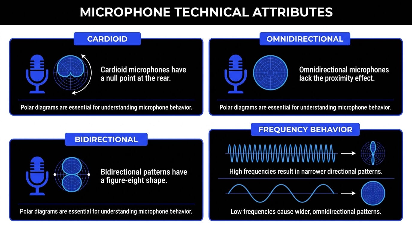
High frequencies have short wavelengths that are easily blocked or reflected by the physical body of the microphone itself. This causes directional microphones to become much narrower and more focused at high frequencies.
Low frequencies have long wavelengths that effortlessly wrap around physical obstacles. As a result, directional microphones exhibit a wider, more omnidirectional pattern at low frequencies.
High-quality technical datasheets plot multiple lines on a single polar diagram, using solid, dashed, and dotted lines to show how the pattern behaves at key frequencies like 125 Hz, 1 kHz, and 4 kHz.
Comprehensive Breakdown of Individual Microphone Polar Patterns
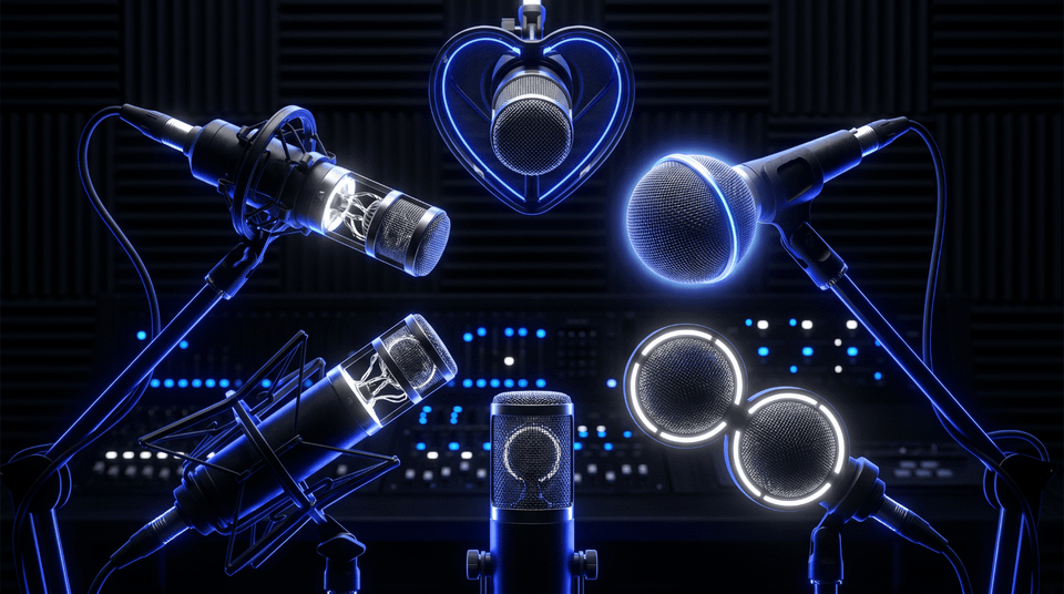
Different recording environments require different directional characteristics. Below is an exhaustive technical breakdown of the six primary microphone polar patterns used in modern audio engineering.

Omnidirectional Pattern
The omnidirectional pattern represents a uniform sphere of sensitivity. The capsule processes sound waves arriving from any direction with equal sensitivity and frequency accuracy.
Acoustic Design Physics
True omnidirectional pickup is achieved using a pressure-operated design where the capsule is closed at the back. Because the diaphragm only reacts to changes in pressure on its front surface, the angle of the incoming sound wave does not affect its movement.
Technical Attributes and Proximity Effect Absence
A key advantage of the omnidirectional pattern is the complete absence of the proximity effect. The proximity effect is an artificial boost in low frequencies that occurs when a directional microphone is placed very close to a sound source. Because pressure-operated capsules do not measure the phase differences between two sides of a diaphragm, they do not experience this low-frequency buildup.
Additionally, omnidirectional microphones are highly resistant to wind noise, plosive vocal pops, and mechanical handling vibrations, making them remarkably stable choices for unpredictable environments.
Ideal Studio and Field Configurations
- Orchestral and Ensemble Recording: Captures a natural, balanced blend of instruments along with the acoustic characteristics of a concert hall.
- Ambient Room Miking: Placed far from a drum kit or guitar amplifier to capture real acoustic room reflections without off-axis coloration.
- Measurement and Calibration: Used for system tuning and acoustic analysis because their flat frequency response is uncompromised by directional phase errors.
Cardioid Pattern
The cardioid pattern is a heart-shaped directional design. It features maximum sensitivity directly in front of the capsule, reduced sensitivity at the sides, and a point of total silence called a null point at the rear.
Acoustic Design Physics
The cardioid pattern combines pressure and pressure-gradient principles in an equal 50-to-50 ratio. By engineering precise rear ports into the capsule, sound arriving from 180 degrees off-axis takes an internal path that arrives at the back of the diaphragm exactly in phase with the sound hitting the front, canceling out the mechanical movement of the diaphragm.
Technical Attributes and Off-Axis Coloration
Cardioid microphones provide excellent front-focused sound isolation, but they are prone to off-axis coloration. Because the internal phase cancellation networks are tuned for specific dimensions, off-axis sounds arriving from the sides are not attenuated evenly across all frequencies. High frequencies are often rejected more aggressively than low frequencies, which can cause off-axis bleed to sound muddy or unnatural.
Ideal Studio and Field Configurations
- Studio Vocal Tracking: Maximizes the direct vocal signal while rejecting unwanted computer fan noise, headphone bleed, and wall reflections.
- Live Stage Performance: Standard for handheld vocal microphones because pointing the rear null directly at stage monitors prevents feedback loops.
- Close Miking Instruments: Isolates individual components of a drum kit, such as the snare drum or toms, by rejecting bleed from adjacent cymbals.
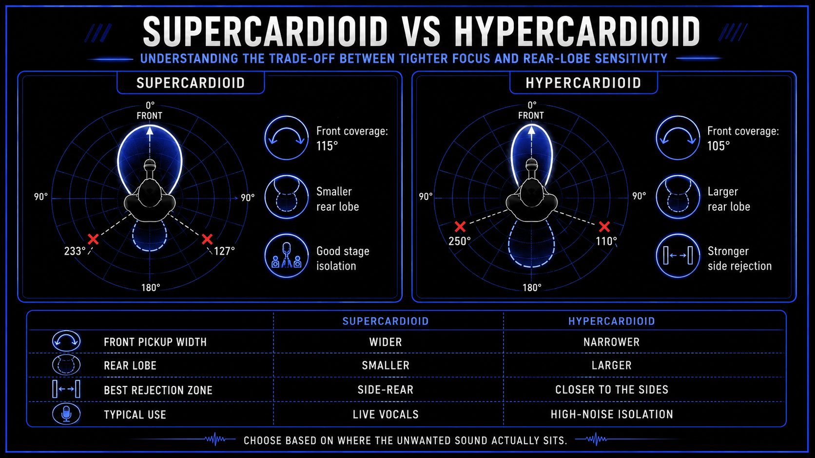
Supercardioid Pattern
The supercardioid pattern offers a tighter, narrower front pickup area than a standard cardioid, but introduces a small rear lobe of sensitivity at the 180-degree mark.
Acoustic Design Physics
This pattern increases the proportion of the pressure-gradient component to roughly 63 percent, with the pressure component making up the remaining 37 percent. This adjustment narrows the front pickup area, but the shift in phase cancellation creates a small secondary pickup lobe pointing directly out the back of the microphone.
Technical Attributes and Null Point Relocation
Because a rear sensitivity lobe forms at 180 degrees, the points of maximum rejection shift away from the absolute back of the microphone. Instead of a single rear null point, a supercardioid microphone features two distinct null points located at approximately 127 degrees and 233 degrees on either side of the rear axis.
Ideal Studio and Field Configurations
- Live Concert Sound Reinforcement: Highly effective when stage monitors are placed to the side of the microphone stand base rather than directly behind it.
- Acoustic Guitar and Vocal Separation: Allows a singer-songwriter to record simultaneously with minimal bleed by angling the side null points toward the competing sound source.
- Snare Drum Bottom Under-Isolation: Narrows the pickup field to capture wire snap while rejecting kick drum spill from below.
Hypercardioid Pattern
The hypercardioid pattern represents an extreme variation of the directional directional microphone design, featuring an ultra-narrow front pickup zone and a significant rear lobe of sensitivity.
Acoustic Design Physics
The hypercardioid pattern pushes the pressure-gradient mix even further, combining 75 percent pressure-gradient behavior with 25 percent pressure operation. This design maximizes side rejection but results in a larger rear lobe that captures significant sound from directly behind the capsule.
Technical Attributes and Proximity Effect Sensitivity
The narrow front pickup area of the hypercardioid pattern provides exceptional sound isolation, but it comes with a strong trade-off: a highly pronounced proximity effect. Even slight movements closer to the microphone capsule trigger a massive increase in low-frequency response, requiring precise performer discipline and careful high-pass filtering.
The two null points of maximum rejection are pushed further toward the sides, sitting at approximately 110 degrees and 250 degrees.
Ideal Studio and Field Configurations
- Intimate Acoustic Sessions: Isolates quiet instruments in multi-musician live room sessions where isolation barriers cannot be used.
- High-Noise Broadcast Environments: Keeps sports announcers clear and intelligible by blocking out loud stadium crowd noise from the sides.
- Drum Overhead Isolation: Captures a focused stereo image of the cymbal kit while blocking spill from guitars and wall reflections.
Bidirectional Pattern (Figure-Eight)
The bidirectional pattern exhibits equal sensitivity at both 0 degrees and 180 degrees, while providing near-perfect sound rejection at the 90-degree and 270-degree sides.
Acoustic Design Physics
A bidirectional microphone uses a pure pressure-gradient design with a completely exposed diaphragm. Sound waves striking the 90-degree sides hit the front and back surfaces with identical force and phase, creating absolute mechanical cancellation and zero electrical output.
Technical Attributes and Symmetric Off-Axis Rejection
The side rejection of a true bidirectional microphone is incredibly sharp and effective across the entire frequency range. Unlike cardioid designs that suffer from muddy off-axis coloration at the sides, a figure-eight microphone rejects side sound evenly across all frequencies, creating a remarkably clean and natural-sounding isolation barrier.
Ideal Studio and Field Configurations
- Face-to-Face Interview Podcasting: Allows two speakers sitting across from each other to talk into a single microphone, saving channels and maintaining a natural balance.
- Advanced Stereo Recording Arrays: Serves as the side microphone component in a Mid-Side stereo matrix, or as both channels in a Blumlein stereo configuration.
- Co-Amplifier Isolation Workflows: Placed between two guitar amplifiers so that the side null zones block out the opposite amplifier sound completely.
Wide Cardioid (Subcardioid) Pattern
The wide cardioid pattern, often called a subcardioid pattern, functions as a hybrid bridge between a completely open omnidirectional response and a standard directional cardioid response.
Acoustic Design Physics
This pattern combines roughly 70 percent pressure operation with 30 percent pressure-gradient mechanics. This mixture yields a broad front pickup area with gentle, subtle attenuation that peaks at only 3 dB to 10 dB of reduction at the 180-degree rear axis.
Technical Attributes and Organic Frequency Response
Wide cardioid microphones offer a beautifully open, uncolored off-axis response and a minimal proximity effect. They provide a touch of front-facing control without introducing the phase artifacts or boxy coloration often found in tight directional capsules.
Ideal Studio and Field Configurations
- Grand Piano Tracking: Captures the massive physical scale and low frequencies of a grand piano without the bass buildup caused by standard cardioid designs.
- Orchestral String Spot Miking: Isolates a section of violins or cellos within a larger mix while preserving a smooth, natural acoustic balance.
- Group Vocal Recording: Seamlessly captures multiple backing vocalists standing around a single microphone capsule.
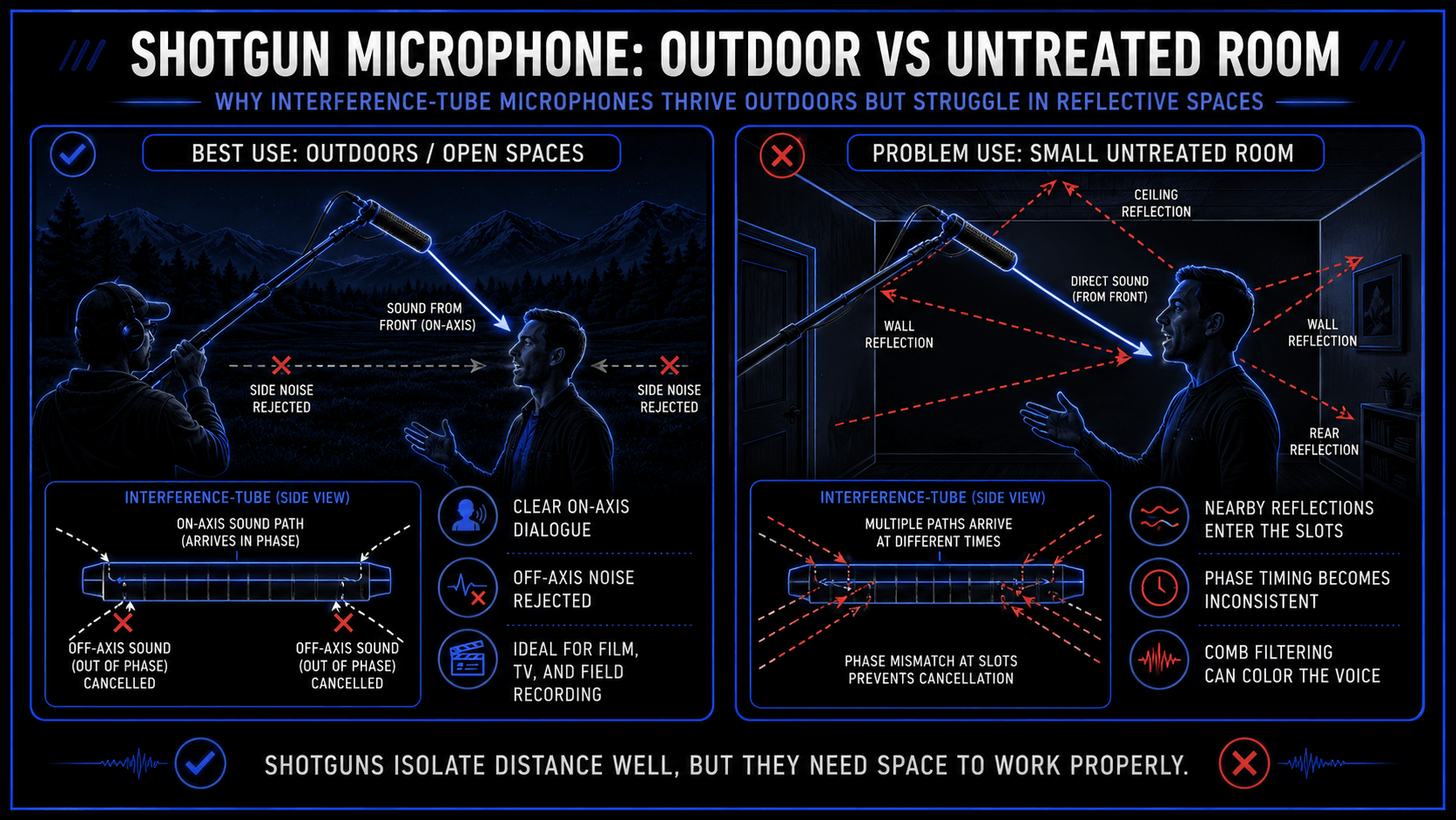
Shotgun (Lobar) Pattern
The shotgun pattern is an ultra-directional, narrow design intended to isolate distant sound sources in highly demanding environments.
Acoustic Design Physics
A shotgun microphone uses a directional supercardioid or hypercardioid capsule placed at the base of a long, hollow tube called an interference tube. The sides of this tube are cut with precisely spaced slots.
When sound waves arrive from the front on-axis angle, they travel straight down the tube without obstruction, striking the diaphragm normally. However, when sounds arrive from off-axis side angles, they enter the tube through multiple side slots simultaneously.
Because the distances from these slots to the diaphragm vary, the sound waves arrive out of phase, canceling each other out before they can move the diaphragm.
Technical Attributes and Long-Distance Limitations
The shotgun microphone provides incredible reach and side isolation, but its complex design makes it highly sensitive to nearby acoustic reflections. If a shotgun microphone is used indoors near low ceilings or hard drywall, off-axis reflections enter the side slots out of phase, creating comb-filtering artifacts that can color the primary audio signal.
Therefore, shotgun microphones are best suited for open outdoor spaces or large, highly treated indoor sound stages.
Ideal Studio and Field Configurations
- Film and Television Field Production: Mounted on a long boom pole just out of camera frame to capture clear dialogue while ignoring ambient traffic and crew noise.
- Outdoor Wildlife and Field Recording: Isolates distant animal calls and natural soundscapes without picking up surrounding environmental noise.
- Distanced Broadcast Journalism: Captures clear, intelligible speech from a reporter standing inside an active press scrum.
Technical Specifications and Advanced Polar Dynamics
To master microphone setup, you need to understand the formal engineering metrics that govern off-axis behavior and sound isolation.
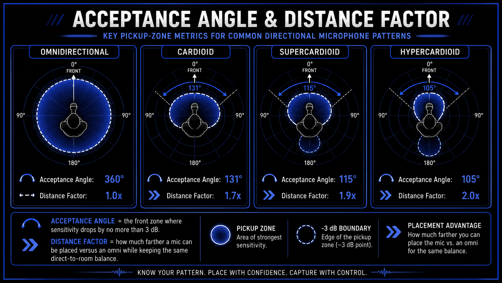
Distance Factor
The distance factor defines how far away a directional microphone can be placed relative to an omnidirectional microphone while maintaining the exact same ratio of direct sound to ambient room reflections.
An engineer using a standard cardioid microphone can position it 1.7 times further from the sound source than an omnidirectional microphone and capture the same balance of room ambiance versus direct signal.
Acceptance Angle (The -3 dB Reduction Point)
The acceptance angle defines the primary usable pickup zone of a microphone. It is measured as the total angle from the center axis within which the microphone sensitivity drops by no more than 3 dB compared to the front on-axis level.
- Cardioid Acceptance Angle: Roughly 131 degrees, offering a wide and forgiving front-facing sweet spot.
- Supercardioid Acceptance Angle: Narrows down to 115 degrees, requiring more precise performer positioning.
- Hypercardioid Acceptance Angle: Narrows further to 105 degrees, requiring absolute performance discipline to avoid dropping out of the pickup zone.
Maximum Reduction and Null Points
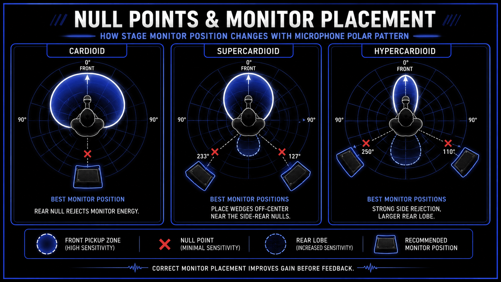
The null points are the precise angles on a polar graph where sensitivity drops to its absolute lowest level, theoretically approaching complete silence. Finding and utilizing these points is critical for managing unwanted background noise:
- Cardioid: Features a single null point located at exactly 180 degrees.
- Supercardioid: Features two symmetric null points located at 127 degrees and 233 degrees.
- Hypercardioid: Features two symmetric null points located closer to the sides at 110 degrees and 250 degrees.
- Bidirectional: Features two massive null zones located at exactly 90 degrees and 270 degrees.
Rear Rejection versus Side Rejection Dynamics
Choosing between a standard cardioid, a supercardioid, or a hypercardioid microphone is a matter of balancing rear rejection against side rejection:
- A standard cardioid microphone provides maximum rejection from directly behind (180 degrees), but it is more sensitive to sounds coming from the 90-degree sides.
- A hypercardioid microphone provides exceptional rejection at the 90-degree sides, but it leaves a significant vulnerability at the 180-degree rear axis due to its large back lobe.
If you are trying to reject a noisy air conditioning vent located directly behind a performer, a standard cardioid is the ideal tool. However, if you are working on a tight live stage trying to reject bleed from loud guitar amplifiers placed to the left and right, a hypercardioid or supercardioid pattern is the superior choice.
Comparative Matrix and Selection Strategy
The comprehensive matrix below summarizes the operational and technical characteristics of each major microphone polar pattern, serving as an engineering feature sheet for studio and live sound configuration.
| Polar Pattern | Front Coverage Angle | Primary Null Angle | Proximity Effect Intensity | Best Application | Ambient Noise Rejection |
|---|---|---|---|---|---|
| Omnidirectional | 360 Degrees | None | Zero | Room Ambiance, Measurement | Minimal Rejection |
| Wide Cardioid | 156 Degrees | 180 Degrees (Weak) | Very Low | Acoustic Guitar, Grand Piano | Moderate Rejection |
| Cardioid | 131 Degrees | 180 Degrees | Moderate | Studio Vocals, Close Toms | High Rear Rejection |
| Supercardioid | 115 Degrees | 127 / 233 Degrees | High | Live Vocals, Stage Isolation | High Rear-Diagonal Rejection |
| Hypercardioid | 105 Degrees | 110 / 250 Degrees | Extreme | Tight Ensemble Isolation | High Side Rejection |
| Bidirectional | 90 Degrees (x2) | 90 / 270 Degrees | High | Mid-Side Stereo, Interviews | Absolute Lateral Rejection |
| Shotgun | 30-50 Degrees | Variable Side Angles | Extreme | Film Set Boom, Outdoor Field | Maximum Off-Axis Rejection |
How ACE Studio Helps When Microphone Polar Patterns Limit the Take
Microphone polar patterns are a physical decision. Once you choose cardioid, omnidirectional, figure-eight, supercardioid, or shotgun, you are deciding what the microphone is allowed to hear. That choice shapes the recording before any plugin, edit, or mix decision happens.
A cardioid microphone can protect a vocal from room reflections. An omnidirectional microphone can preserve the full size of a piano or string ensemble. A figure-eight microphone can reject side noise with sharp null points. A shotgun microphone can isolate dialogue outdoors. Each pattern gives you control, but each one also leaves something behind.
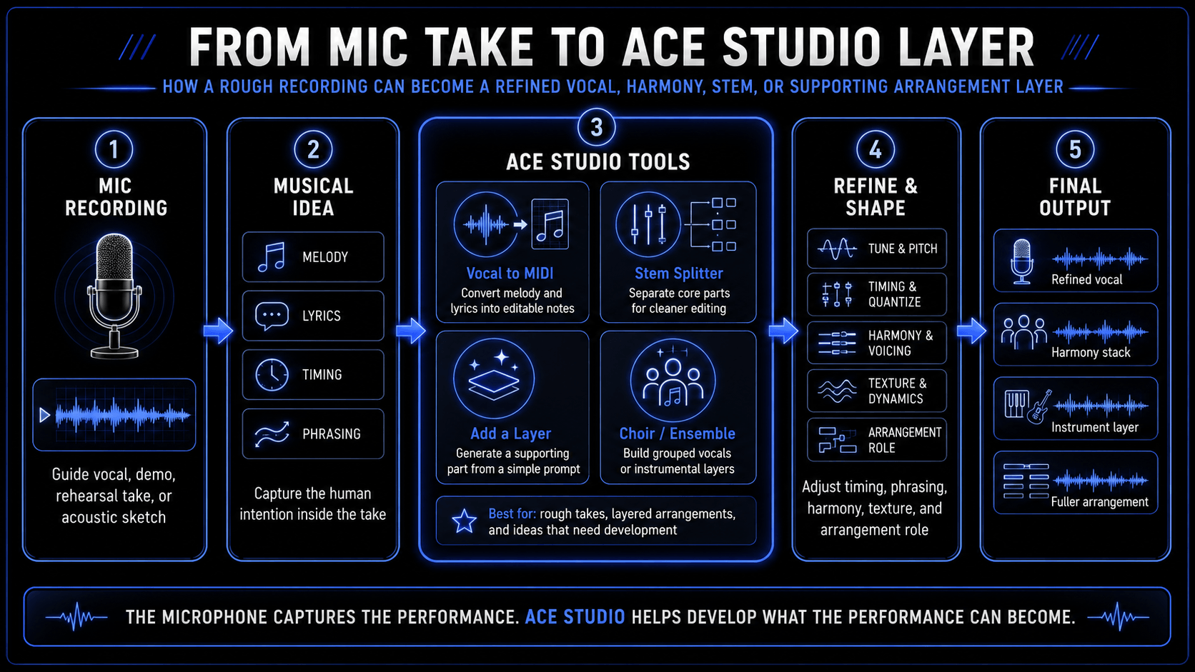
That is where ACE Studio becomes useful – not as a replacement for microphone technique, but as a second layer of musical control when the recording does not give you everything the song needs.
A polar pattern can isolate a source, but it cannot rewrite the performance. If you recorded a guide vocal with a cardioid mic and the tone is focused but the phrasing needs work, ACE Studio gives you a way to turn the musical idea into something editable. Its Vocal to MIDI tool can convert a vocal line into MIDI notes and lyrics, so the melody, timing, and lyric placement can be refined instead of being locked inside the original audio take. ACE Studio also generates singing vocals from MIDI and lyrics, which means the original mic recording can become the sketch that guides a cleaner, more controlled vocal performance.
This is especially useful in the same situations where polar pattern choice matters most:
| Recording situation | What the polar pattern does | Where ACE Studio helps |
|---|---|---|
| Bedroom vocal with room reflections | Cardioid reduces rear pickup | Rebuild or refine the vocal idea from MIDI and lyrics |
| Singer-songwriter demo with guitar bleed | Directional mic improves separation | Use the captured melody as editable material |
| Group vocal idea without enough singers | Omni or wide cardioid captures a natural blend | Build controlled backing vocals or choir parts |
| Acoustic track needs extra depth | The mic captures the real instrument and room | Add a supporting layer from a simple prompt, then refine it around the original take |
| Instrument part missing from the arrangement | Mic choice cannot create a new performance | Add MIDI-driven AI instruments with articulation control |
| Mixed rehearsal recording | Polar pattern choice is already baked in | Stem Splitter can separate core parts for further editing |
The important point is that ACE Studio does not “fix” a polar pattern after the fact. If an omnidirectional mic captured too much room, or a hypercardioid rear lobe picked up a wall reflection, that acoustic information is part of the recording. ACE Studio is more useful when the musical idea inside that recording is worth developing.
For example, imagine a songwriter records a rough vocal and acoustic guitar with one cardioid microphone. The cardioid pattern helps focus the voice, but the guitar still bleeds into the vocal track. Instead of forcing that rough take to become the final vocal, the producer can use the take as a musical map: extract the melody, refine the timing, adjust the phrasing, and test a different vocal tone. The original recording still matters because it carries the human intention. ACE Studio simply gives that intention more room to be shaped.
The same logic applies beyond vocals. The AI instruments including strings, saxophones, trumpets, and duduk, with articulation control for more nuanced performances. That matters for producers who understand microphone polar patterns because some sounds are hard to capture well at home. A real violin section, brass layer, or cinematic support part usually depends on the right room, performers, mic distance, stereo technique, and noise control.
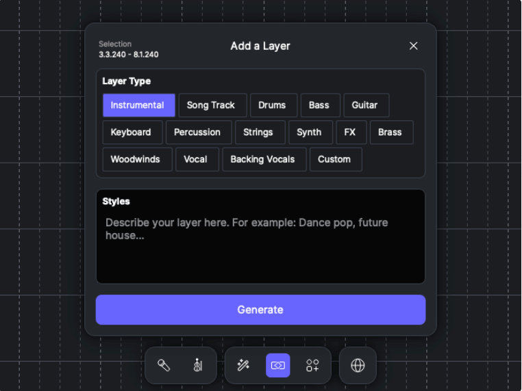
With ACE Studio, a producer can write the part in MIDI, shape the performance directly, or use the Add a Layer feature to quickly generate a supporting part via simple prompt, and build it into the arrangement without setting up another microphone. Instead of forcing a rough overdub into the track, you can create a cleaner layer that supports the original recording.
A good use case is an acoustic track recorded with a wide cardioid or omnidirectional mic. The recording may have a beautiful natural image, but the chorus needs a string response or soft vocal pad. Rather than crowding the original track with more poorly recorded overdubs, ACE Studio can add a controlled instrumental or choir layer around the captured performance. The microphone preserves the real acoustic center. ACE Studio adds the parts that would be difficult to record with the same quality in the same space.
There is also a practical connection to figure-eight and stereo thinking. A figure-eight microphone is valuable because of its side rejection and front-back sensitivity. That teaches producers to think in layers: what should sit in front, what should answer from behind, and what should stay out of the sides. ACE Studio’s Choir Mode and Ensemble Mode can support that same arrangement mindset. You can build grouped vocal or instrumental parts with intention, then decide whether they should feel close, wide, supportive, or dramatic before exporting them into the mix.
For film and video creators, the polar pattern conversation often leads to shotgun microphones. Shotguns are chosen when the goal is focus: dialogue, movement, outdoor scenes, or sound that must stay connected to the frame. ACE Studio’s Video Composer gives another option after the production sound is captured. It can import video directly and help create music or sound effects matched to the video content. That does not replace location audio, but it helps complete the sonic world around it when the microphone captured only the necessary dialogue or field sound.
The microphone decides what enters the recording. ACE Studio helps you decide what that recording can become – a refined vocal, a cleaner guide, a harmony stack, a string layer, a separated stem, or a fuller arrangement. The producer still makes the decisions. The singer, player, melody, lyric, and performance direction remain human-led.
Production Applications and Creative Recording Techniques
Translating technical specifications into professional recordings requires a strategic understanding of how polar patterns interact with real instruments and physical spaces.
Vocal Capture Strategies
When recording vocals, determining what polar pattern is best for vocals depends heavily on the room acoustics and the performance style:
- In an Untreated Home Studio: Avoid using omnidirectional or hypercardioid patterns. An omnidirectional pattern captures too much untamed room reflection, while a hypercardioid rear lobe points directly at the walls behind the singer, picking up slapback echoes. Stick to a standard cardioid microphone placed close to the vocalist to maximize the direct signal and reject the room.
- In a High-End Commercial Tracking Room: If a vocalist has exceptional control and the room acoustics sound beautiful, try switching to an omnidirectional pattern. The absence of the proximity effect allows the singer to move naturally without shifting the bass balance, resulting in an open, organic vocal sound that blends effortlessly into a mix.
Acoustic Instrument and Amplifier Tracking
- Acoustic Guitar Configuration: Using a single cardioid microphone placed 8 inches away and aimed at the 12th fret is a reliable standard. However, if you want a wider, more spacious sound, use a stereo pair of omnidirectional microphones spaced two feet apart. This captures the complete resonance of the wood instrument along with natural room reflections.
- High-SPL Guitar Amplifiers: Place a rugged dynamic cardioid microphone close to the speaker grille cloth, positioned halfway between the center cap and the outer edge of the cone. This positioning captures a punchy, direct sound while using the close distance to naturally reject bleed from other instruments in the live room.
Broadcast, Podcasting, and Live Performance Environments
- Live Concert Sound Reinforcement: Managing gain-before-feedback is the primary challenge in live sound reinforcement. Monitor wedges must be aligned precisely with the null points of the stage microphones. When using a standard cardioid microphone like the Shure SM58, place the monitor wedge directly behind the microphone stand at 180 degrees. If you switch to a supercardioid vocal microphone, place the monitor wedges off to the sides at 120 or 130 degrees to line up with the pattern true null points.
- Dual-Host Podcasting on a Budget: Instead of buying two separate setups, place a single bidirectional microphone sideways between both speakers. The hosts talk into the front and back lobes at 0 and 180 degrees, while the side null points at 90 and 270 degrees face the room walls, blocking out computer fan noise and echo.
Frequently Asked Questions
Why does a microphone polar pattern change at low frequencies?
Polar patterns become wider at low frequencies because of the physical relationship between sound wavelengths and capsule dimensions. Low bass frequencies have long wavelengths that can easily wrap around physical obstacles like a microphone casing. This reduces the phase differences between the front and back of the diaphragm, causing directional microphones to exhibit an omnidirectional response at low frequencies.
Can I change a microphone polar pattern after a track has been recorded?
If you used a standard, single-output microphone, its polar pattern is permanently baked into the audio file and cannot be changed. However, if you record using a multi-capsule modeling microphone that captures separate outputs from each diaphragm, you can use software plugins to alter the polar pattern dynamically during the mix phase.
How does the proximity effect relate to different polar patterns?
The proximity effect is tied directly to pressure-gradient mechanics. Pure pressure-gradient designs, like bidirectional figure-eight microphones, exhibit the strongest low-frequency boost when placed close to a sound source. Hybrid patterns like hypercardioid and cardioid show a moderate proximity effect, while true pressure-operated omnidirectional microphones do not experience the proximity effect at all.
What is the difference between a null point and an acceptance angle?
The acceptance angle defines the front-facing usable pickup zone where the microphone signal drops by no more than 3 dB. A null point is the exact opposite: it is the specific angle where the internal phase cancellation is strongest, causing the microphone sensitivity to drop to its lowest possible level to reject unwanted sound.
Why do shotgun microphones perform poorly inside small, untreated rooms?
Shotgun microphones rely on an interference tube with side slots to cancel out off-axis sound waves. In a small, untreated room, sound reflections bounce off the nearby walls and ceiling, entering the side slots from multiple random angles simultaneously. This disrupts the phase cancellation timings, causing comb filtering that can discolor the primary on-axis audio.