Technical Guide to Phantom Power in Professional Audio Production

Key Takeaways
- Phantom power sends 48V DC through a balanced XLR cable to power condenser microphones, active DI boxes, inline boosters, and other active studio devices without needing extra power cables.
- Condenser microphones need phantom power because their capsules and internal impedance-conversion circuits require electrical support to capture a clean, usable signal.
- Properly wired passive dynamic microphones are generally safe with phantom power, but vintage ribbon microphones, faulty XLR cables, unbalanced connections, and hot-plugging can create real equipment risks.
- Weak or unstable phantom power can reduce headroom, raise the noise floor, lower sensitivity, and cause distortion, especially when using multiple condenser microphones on budget or bus-powered interfaces.
- Phantom power helps capture a clean recording at the hardware stage, while tools like ACE Studio can help reshape, arrange, and extend recorded vocals, instruments, stems, and MIDI after the sound is inside the session.
The power system behind clean microphone recording
In professional audio engineering, the transmission of electrical energy to transducer systems without adding extra cabling is a cornerstone of modern recording studio design. This technique, universally known as phantom power, allows high-fidelity microphone systems and active signal-conditioning electronics to operate seamlessly within standard balanced audio lines.
Understanding the operational principles, historical context, and troubleshooting protocols of this technology is essential for sound engineers, system designers, and content creators who want to maintain signal integrity and protect delicate audio equipment.
Fundamentals of Audio Phantom Power
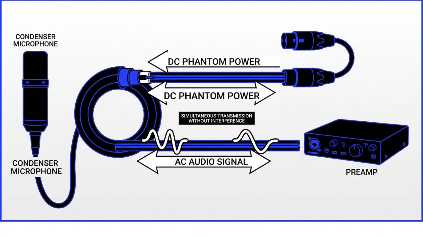
The standard phantom power definition describes a method of distributing direct current (DC) electrical power through balanced microphone cables to operate electronic components within acoustic transducers and active utility devices. This process occurs simultaneously with the transmission of alternating current (AC) audio signals without causing interference or degradation to the audio waveform.
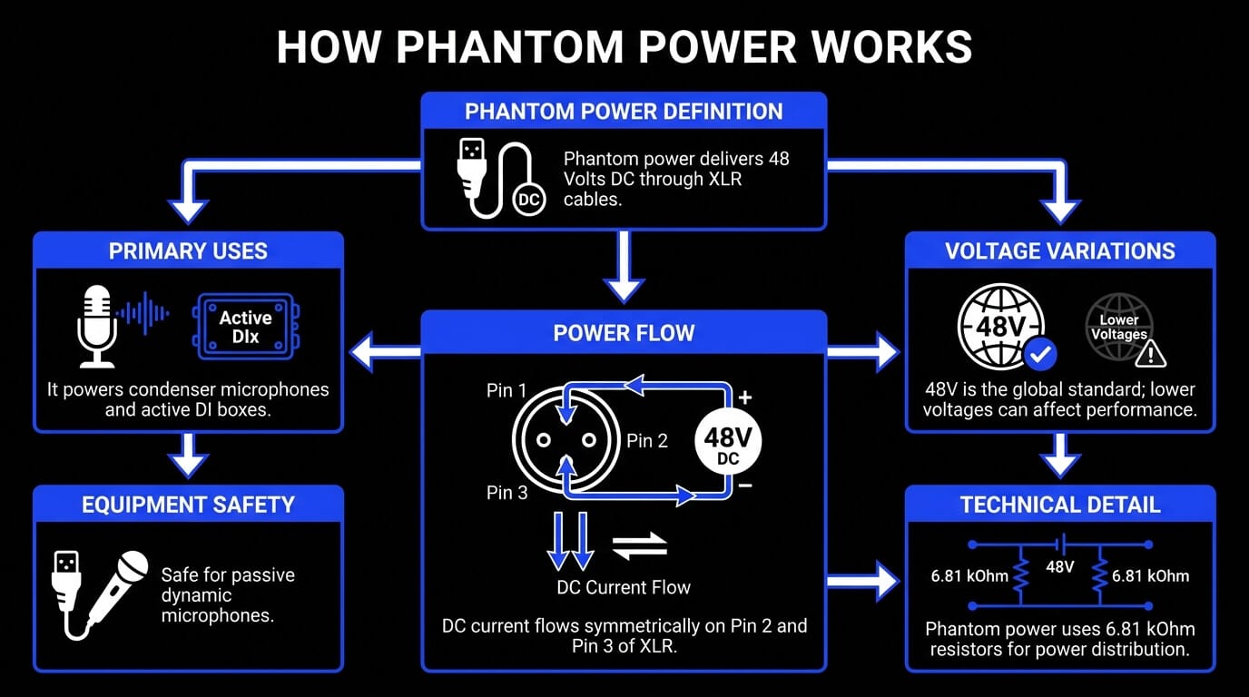
When analyzing microphone phantom power, the electrical system delivers a positive direct current voltage equally across the two signal-carrying conductors of a balanced line, utilizing the cable shield or ground wire as the return path for the electrical circuit.
The fundamental audio phantom power concept relies entirely on electrical symmetry. Because the voltage potential on the two signal lines is perfectly identical relative to the ground reference, the net potential difference between the two active signal conductors is zero volts.
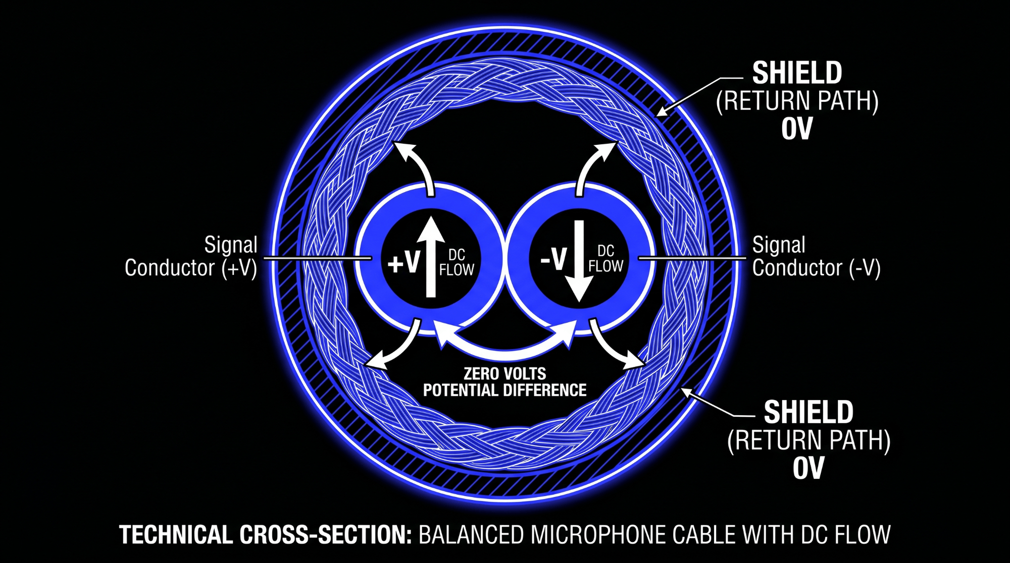
Consequently, any downstream audio components that measure the signal differentially between the two active wires remain completely unaffected by the presence of the direct current voltage. This design constitutes a highly stable, low-noise power distribution system perfectly suited for the rigorous demands of professional recording studio installations and complex live sound reinforcement environments.
Operational Mechanics of Phantom Power Supply
How Audio Cables Carry Alternating Current and Direct Current Simultaneously
The coexistence of direct current (DC) power and alternating current (AC) audio signals on a single balanced three-pin XLR cable is an elegant application of basic linear network theory. A professional balanced audio connection relies on three distinct conductors:
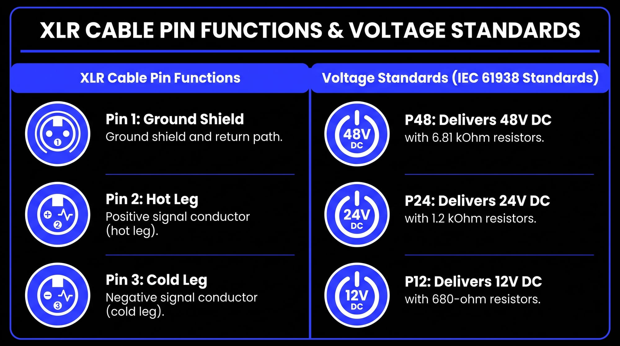
- Pin 1: The ground shield, which acts as the electrostatic chassis shield and the electrical return path.
- Pin 2: The positive signal conductor, often designated as the hot leg, which carries the non-inverted audio signal.
- Pin 3: The negative signal conductor, often designated as the cold leg, which carries an identical audio signal inverted 180 degrees in phase.
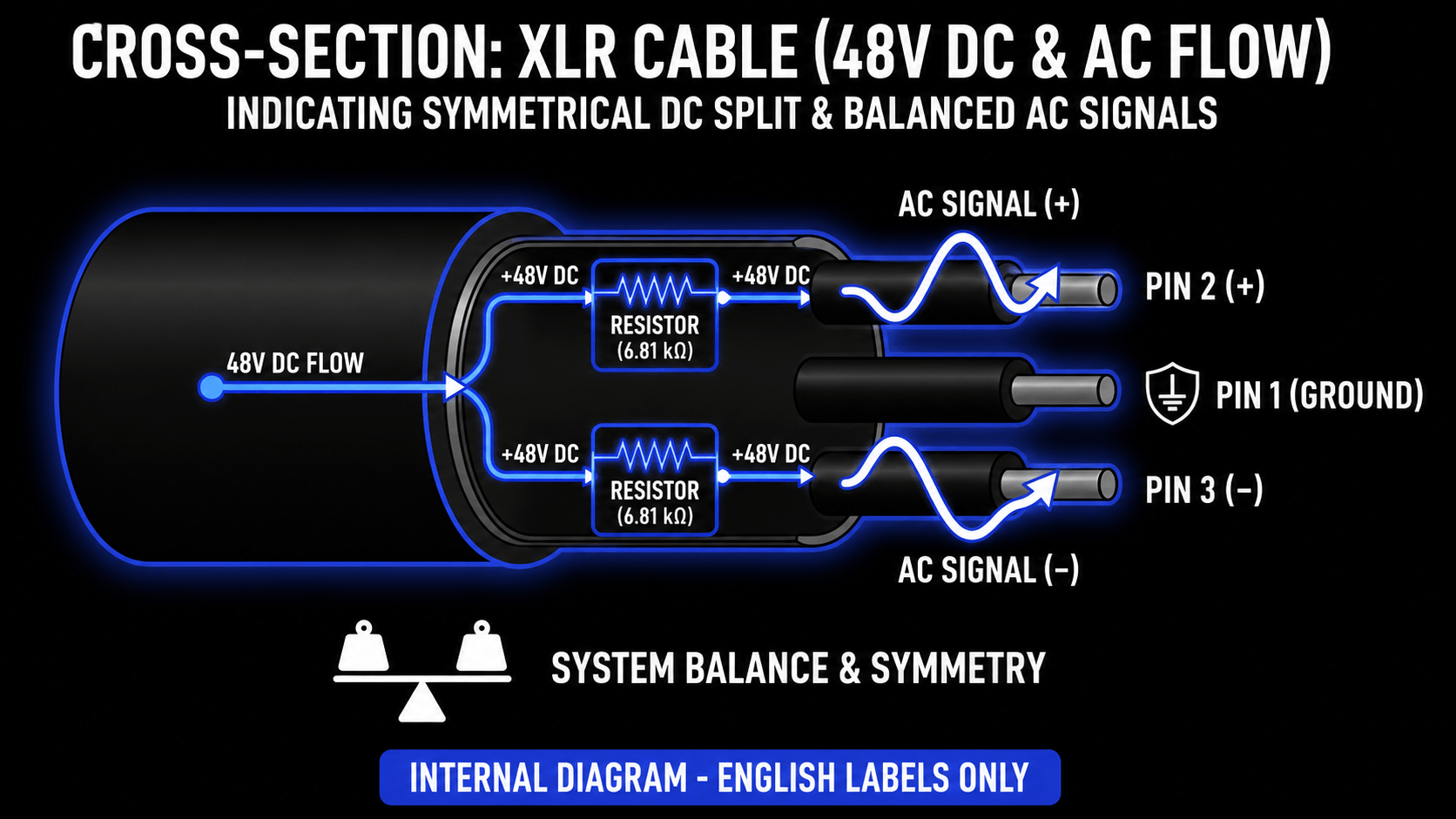
Within the phantom power supply circuit, a 48-volt direct current source is split and applied equally to Pin 2 and Pin 3. This connection is made through two precision-matched resistors, each possessing a nominal resistance of 6.81 kilohms.
When the cable connects to a microphone, the direct current flows out from the preamp through these resistors, travels symmetrically along Pin 2 and Pin 3, passes through the microphone internal electronic components, and returns to the source device via the Pin 1 ground shield connection.
Simultaneously, the microphone transducer capsule generates an acoustic-driven alternating current voltage. This audio voltage is driven differentially between Pin 2 and Pin 3. As a result, the audio signal oscillates as a voltage difference between the two hot and cold lines.
Because the direct current voltage is static and identical on both lines, it does not alter this differential voltage relationship. At the receiving microphone preamplifier or audio interface input stage, the input circuit utilizes either an audio transformer or a differential electronic operational amplifier to subtract the signal on Pin 3 from the signal on Pin 2.
This mathematical subtraction eliminates the identical 48-volt direct current component completely through common-mode rejection, while doubling the amplitude of the alternating current audio signal.
Voltage Standards and Variations
While 48V phantom power represents the global benchmark, international engineering standards recognize three primary variations. The IEC 61938 standard defines the following operational profiles:
- P12: Delivers 12 Volts DC through matched 680-ohm resistors.
- P24: Delivers 24 Volts DC through matched 1.2-kilohm resistors.
- P48: Delivers 48 Volts DC through matched 6.81-kilohm resistors.
Among these specifications, P48 has achieved absolute dominance in professional recording studio and sound engineering applications. However, hardware deviations frequently occur in consumer-grade audio interfaces, field recorders, and budget mixing consoles.
Many bus-powered electronic devices struggle to step up their native 5-volt USB bus voltage to a stable 48-volt rail under full current load. Consequently, some consumer units deliver lower voltages, dropping down to 32 volts or even 12 volts when multiple microphones are connected simultaneously.
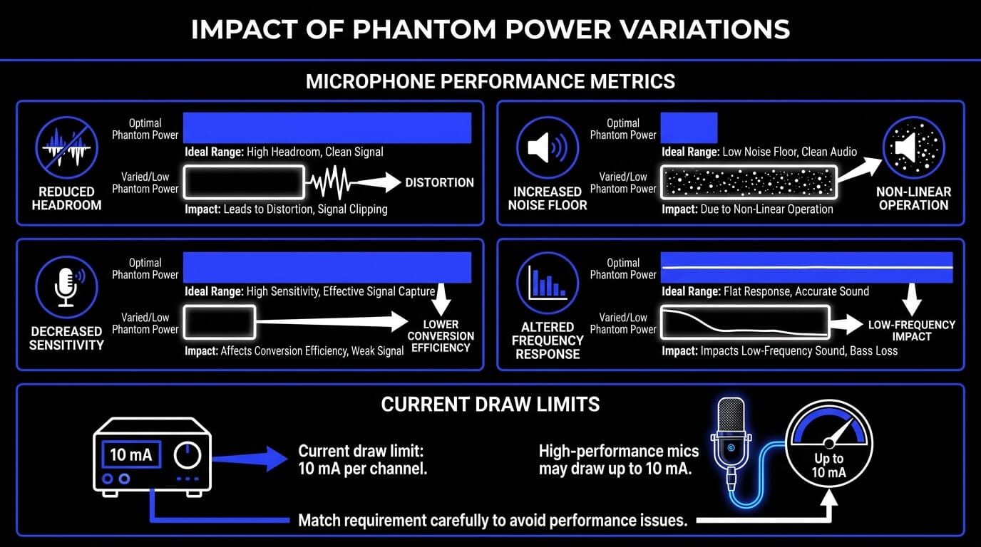
When a high-performance condenser microphone receives a voltage significantly lower than its specified 48-volt requirement, its internal operating parameters are compromised. The consequences of an under-voltage supply include:
- Reduced Headroom: The internal preamplifier circuitry clips prematurely, distorting high-amplitude transient signals.
- Increased Noise Floor: Signal amplification stages within the microphone operate outside their linear region, introducing thermal and electronic noise.
- Decreased Sensitivity: The electrostatic polarization charge on the non-electret capsule drops, reducing the acoustic-to-electric conversion efficiency.
- Altered Frequency Response: The microphone low-frequency extension and transient accuracy suffer due to inadequate damping control in the internal active circuitry.
Current Drawing Limits and Microphonic Requirements
The maximum current draw permitted under the international IEC 61938 specification for a P48 phantom power system is 10 milliamperes (mA) per individual channel.
Modern solid-state condenser microphones typically demand between 1 and 5 milliamperes under standard operating conditions. For example, a standard studio vocal condenser microphone might draw approximately 3.2 milliamperes to power its internal field-effect transistor impedance converter and DC-to-DC step-up converter circuit.
However, specialized measurement microphones, high-headroom studio models, and microphones utilizing internal microprocessor control systems can draw up to the full 10-milliampere threshold.
If a connected device attempts to draw current in excess of the power supply capability, or beyond the limits dictated by the 6.81-kilohm current-limiting feeding resistors, a significant voltage drop occurs across those resistors. This drop starves the microphone electronics, destabilizing the active components and rendering the audio signal highly distorted or completely muted.
Impedance Impact within P48 Circuitry
The integration of a phantom power supply network introduces a specific electrical load that alters the input impedance of a microphone preamplifier channel. In a standard P48 configuration, the two 6.81-kilohm feeding resistors are connected in parallel.
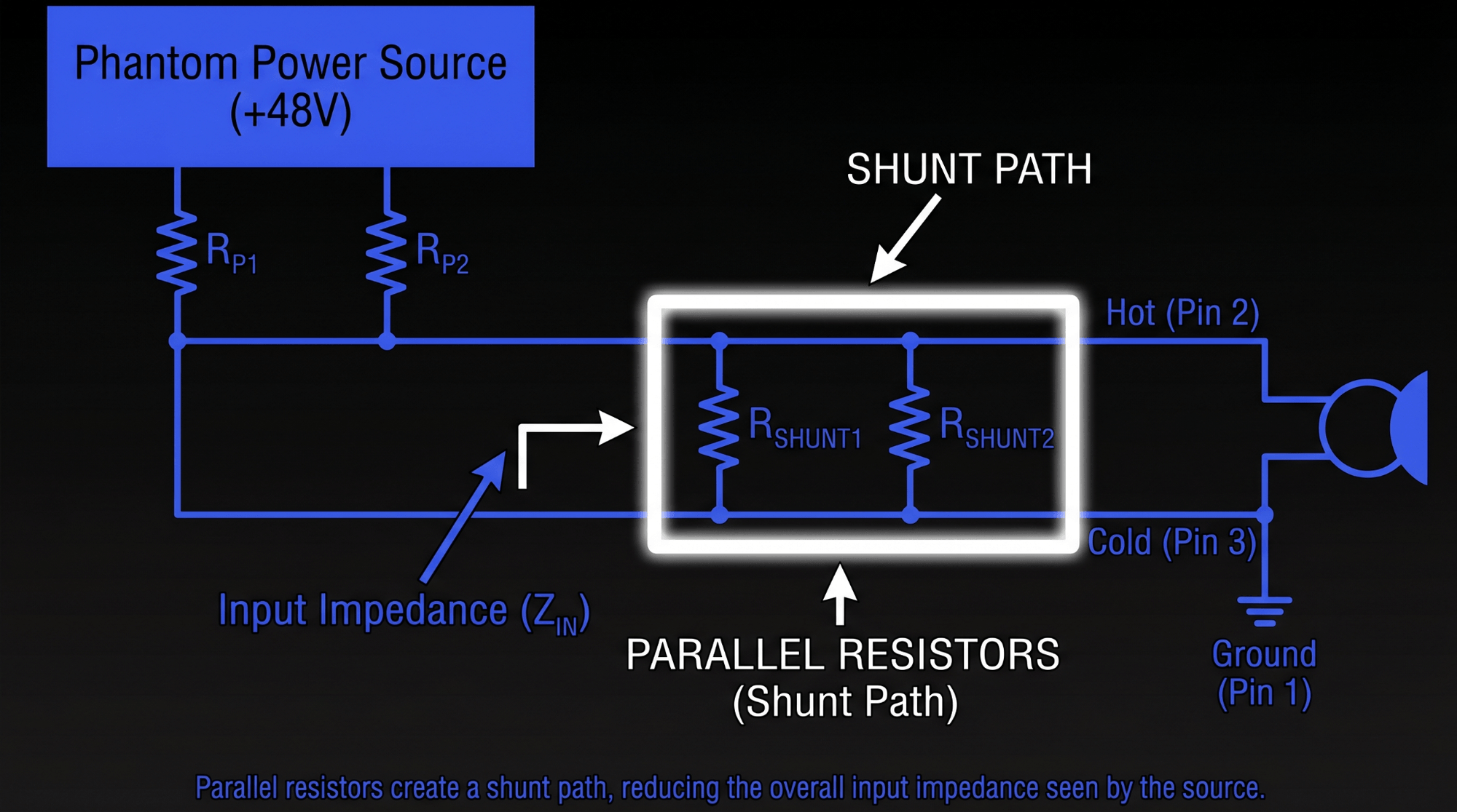
This parallel configuration introduces an electrical shunt path across the balanced input line. Calculating the equivalent resistance of these two parallel paths yields an effective resistance of 3.405 kilohms.
This resistance sits directly across the nominal input impedance of the preamplifier input stage, which typically ranges from 1.5 kilohms to 3 kilohms in standard professional gear.
Because this phantom power network resistance works in parallel with the preamplifier native input impedance, it lowers the overall input impedance seen by the output stage of the connected microphone.
This modification to the impedance ratio can subtly influence the high-frequency response and transient damping characteristics of certain passive microphones, such as older dynamic and ribbon models, if they are connected to a preamp with phantom power engaged.
Electroacoustic Requirements for Microphones
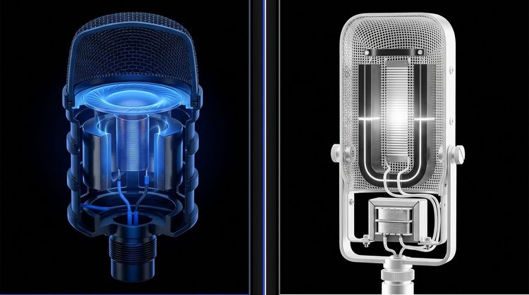
The Operational Necessity of Power in Condenser Microphones
Condenser microphones function on electrostatic principles rather than the electromagnetic induction principles used by dynamic microphones. The capsule of a condenser microphone consists of two distinct components: a highly flexible, micro-thin gold-sputtered Mylar diaphragm placed in close proximity to a solid, fixed metal backplate. Together, these two parallel elements form a variable acoustic capacitor.
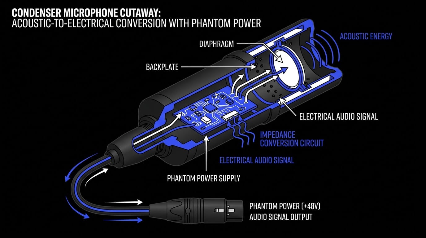
To convert acoustic sound waves into an electrical signal, this capacitor capsule must contain an electrical charge. There are two primary ways this charge is maintained:
- True Condenser Microphones: These require a constant external polarization voltage, usually supplied by the phantom power system. This voltage puts a continuous electrical charge on the capsule. When acoustic pressure waves hit the flexible diaphragm, it moves closer to and further from the fixed backplate, changing the capacitance of the system. Since the electrical charge is held constant, this changing capacitance creates a corresponding alternating current voltage that mirrors the acoustic waveform.
- Electret Condenser Microphones: These feature a pre-polarized capsule material that holds a permanent electrostatic charge, meaning they do not need phantom power to charge the capsule itself. However, they still require phantom power to run their internal active electronics.
Regardless of how the capsule is polarized, the output impedance of a condenser capsule is incredibly high, often measuring in the gigaohm range. This ultra-high impedance makes the raw signal highly vulnerable to signal loss and noise over even an inch of standard wire.
To resolve this, every condenser microphone includes an internal impedance conversion circuit, typically utilizing a low-noise field-effect transistor or a vacuum tube. This circuit converts the unmanageable gigaohm signal from the capsule down to a stable, low-impedance format (usually under 200 ohms) suitable for transmission over long XLR cables.
Without phantom power to energize this internal impedance converter and its output amplification stage, the microphone cannot pass any audio signal.
Miniature Microphones and Specialized Electret Systems
Miniature microphones, such as lavaliers, head-worn theatrical microphones, and small instrument clip-on systems, are almost exclusively electret condenser designs. Because of their tiny size, these miniature capsules cannot fit the large electronic components or standard three-pin XLR connectors used in full-sized studio microphones. Instead, they typically terminate in smaller, proprietary multi-pin connectors like TA4F, sub-miniature TRS jacks, or Lemo connections.
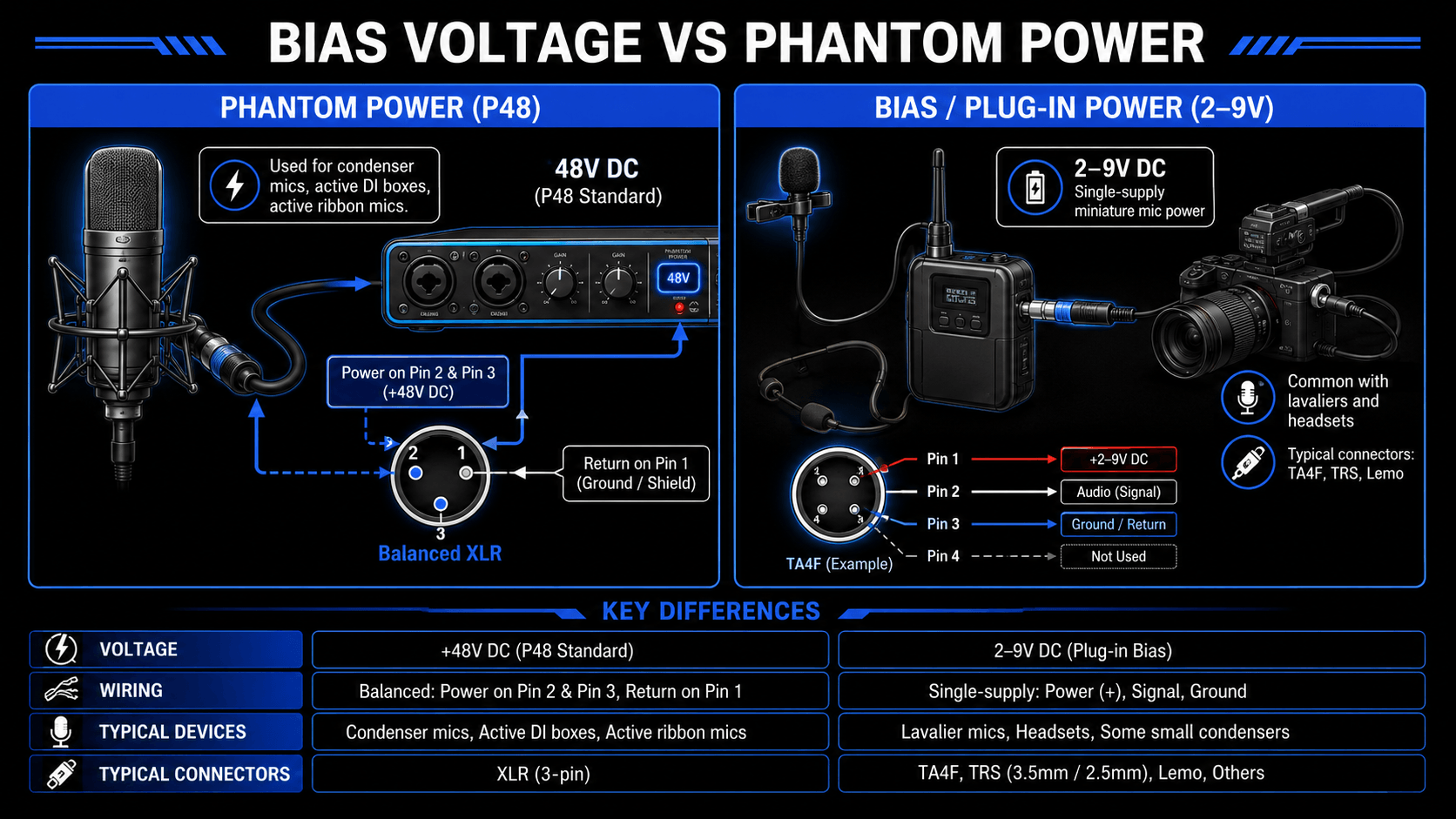
These miniature microphones do not run directly on 48V phantom power. Instead, they require a much lower direct current voltage, usually between 2 and 9 volts DC, which is known as bias voltage or plug-in power.
Bias voltage is delivered over a single signal wire, sharing the path with the audio signal, rather than being split evenly across a balanced pair like true phantom power.
To use these miniature microphones with professional studio gear, you must connect them through a specialized power adapter or wireless bodypack transmitter.
When using a wired XLR adapter, the adapter connects directly to a standard 48V phantom power preamp. The electronics inside the adapter step down the 48-volt current to a safe 5-volt bias voltage, while also converting the microphone unbalanced output into a balanced signal suitable for long cable runs.
Comparative Analysis: Phantom Power vs. Battery Power
Before phantom power became standard on modern audio interfaces, internal battery power was a common alternative for powering field condenser microphones. The table below outlines the core functional differences between these two power delivery methods:
| Feature Specification | Phantom Power Distribution (P48) | Internal Battery Power System |
|---|---|---|
| Voltage Stability | Exceptionally high; driven by regulated mains or interface rails. | Degrading; voltage drops continuously as the battery cell depletes. |
| System Headroom | Maximum potential; supports wide dynamic ranges without clipping. | Restrained; limited by the native voltage of the battery cell (e.g., 1.5V or 9V). |
| Operational Reliability | Permanent continuous operation; no risk of sudden depletion during recording. | Risk of mid-session failure; requires manual checking and replacement. |
| Physical Weight & Form | Zero impact on microphone chassis weight or footprint. | Increases microphone weight and size to accommodate battery compartments. |
| Environmental Impact | Low; draws efficient power from the primary audio system hardware. | Higher; generates chemical waste through depleted disposable batteries. |
Practical Applications and System Integration
Benefits of Phantom Power in Audio Recording
The integration of phantom power into professional audio systems offers substantial advantages for modern studio workflows and live sound production:
- Streamlined Workspace Infrastructure: By carrying power directly over standard XLR cables, studios eliminate the need for bulky external power supplies and extra power cables. This drastically reduces clutter around microphone stands and instrument setups.
- Optimal Signal Amplification: Delivering a consistent 48-volt supply allows the internal preamplifiers of condenser microphones to operate at peak linearity. This maximizes the microphone dynamic range, ensures ultra-fast transient response, and keeps the self-noise floor exceptionally low.
- Universal System Compatibility: The standardized P48 architecture ensures that any compliant condenser microphone can be safely connected to any standard audio interface or mixing console worldwide, creating an ecosystem of predictable plug-and-play compatibility.
Ancillary Devices that Use Phantom Power
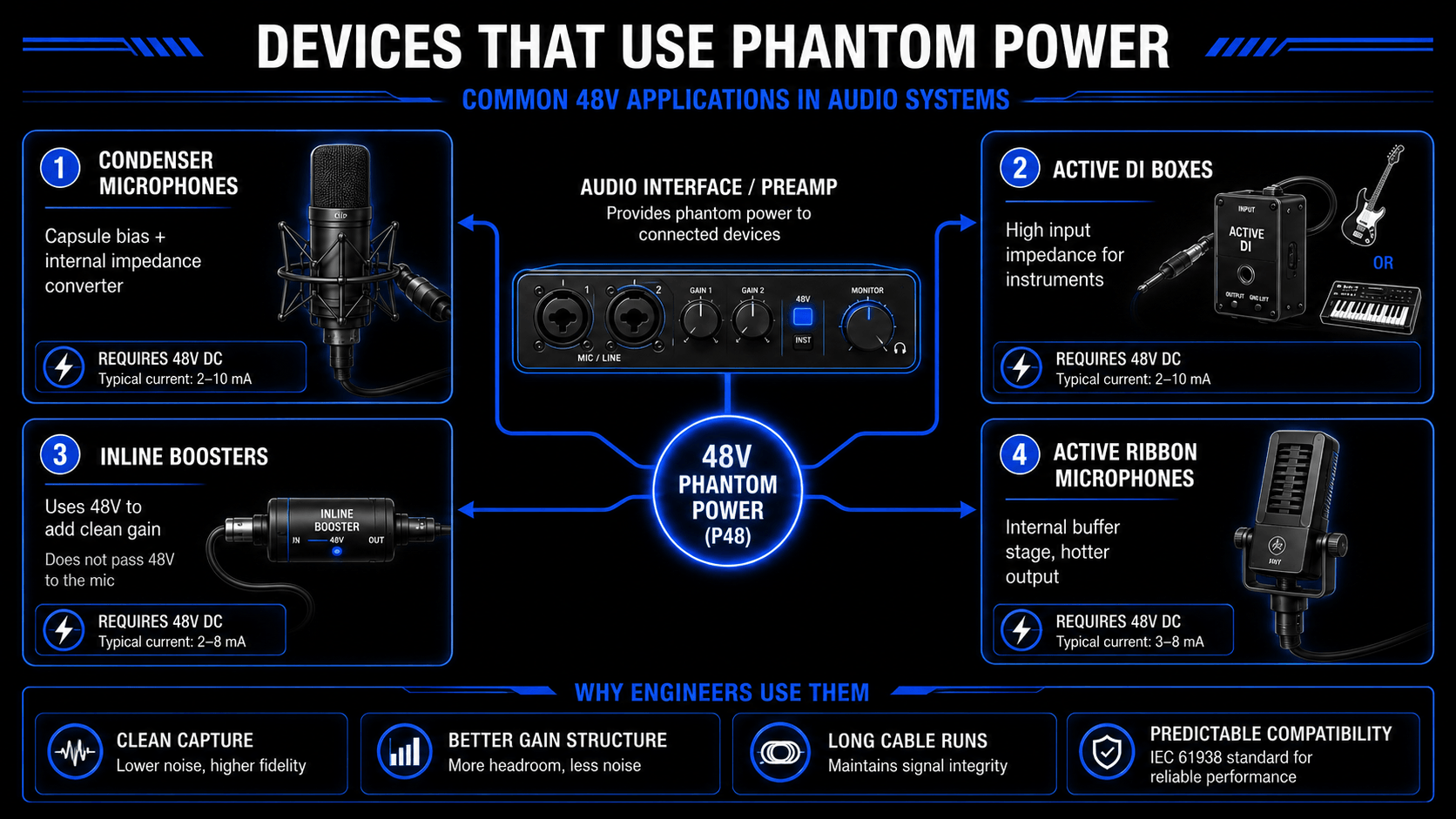
While phantom power was originally engineered exclusively for condenser microphones, modern audio equipment manufacturers utilize this convenient power source for a wide variety of active utility electronics within the recording studio setup.
Active Direct Injection (DI) Boxes
Passive DI boxes use transformers to convert high-impedance instrument signals (like electric bass or keyboards) to low-impedance microphone signals. Active DI boxes, however, replace or augment these transformers with active electronic circuitry.
Using phantom power, these active units achieve exceptionally high input impedance, preventing high-frequency roll-off and preserving the natural tone of passive instrument pickups over long cable runs.
Inline Microphone Preamplifiers and Signal Boosters
Devices like the Cloudlifter, FetHead, or Dynamite use phantom power to run high-gain, ultra-clean internal amplification circuits. These inline boosters do not pass phantom power through to the microphone.
Instead, they consume the 48-volt current to provide a clean, fixed gain boost (typically +20dB to +28dB) before the signal reaches the main preamp. This is highly beneficial for low-output passive microphones, such as classic dynamic or ribbon models, when paired with entry-level preamps.
Active Ribbon Microphones
Traditional ribbon microphones are entirely passive and vulnerable to damage from phantom power. Modern active ribbon microphones, however, feature internal electronic buffer stages similar to those found in condenser microphones.
These modern designs use phantom power to run their internal electronics, which protects the delicate ribbon element from impedance mismatching and provides a hotter, more consistent output level.
How ACE Studio Extends the Recording Process After Phantom Power
Phantom power solves one important part of recording: it gives condenser microphones and active studio devices the clean electrical support they need to capture a stable signal. But once that signal is recorded, the creative decisions are still in your hands.
ACE Studio is not a replacement for microphones, singers, instrumentalists, or careful recording technique. Think of it as a production space where recorded audio, MIDI, lyrics, stems, and instrument parts can be shaped after the capture stage. A clean condenser recording powered by 48V phantom power gives you a strong starting point. ACE Studio helps you take that starting point further without forcing you into a one-click result.
For example, if you record a rough vocal idea through a condenser microphone, ACE Studio can help turn that idea into an editable musical part. Its AI Singing Vocal Generator can create vocals from MIDI notes and lyrics, and the voice controls let you adjust notes, phonemes, pitch, and vocal expression instead of accepting a flat generated take. ACE Studio’s current Voice Library is built around AI voices that can be shaped through MIDI and lyrics, with controls for pitch and vocal parameters.

This is especially practical when a song idea is strong but the original recording is only a sketch. You can capture the melody with whatever mic setup you have, then use tools such as Stem Splitter and Vocal-to-MIDI to separate or convert parts for editing, which makes it easier to move from recorded audio into editable musical material.
ACE Studio also goes beyond vocals. If your phantom-powered mic captured an acoustic guitar, piano room idea, topline, or guide vocal, you can build around it with AI instruments, ensembles, and prompt-based generative layers. ACE Studio 2.0 added AI instruments such as violins, violas, cellos, saxophones, trumpets, and duduk, with articulation control for more nuanced performances. Its Instrument Library is designed for adding AI instruments and ensembles directly into a project. While the Generative Kits can create loops, samples, and layers from a simple prompt, which you can trim, arrange, and refine.
A practical example would be a songwriter recording a quiet vocal and guitar demo with a condenser microphone. Phantom power keeps the mic operating properly. ACE Studio can then help separate the vocal, convert a melody into MIDI, test different vocal tones, add a string layer, or build a supporting instrumental part around the original idea. The songwriter still decides the melody, phrasing, lyrics, harmony, and emotional direction. ACE Studio simply gives more material to shape.
For producers working in a DAW, ACE Bridge can connect ACE Studio with major plugin formats including VST3, AU, and AAX, supporting audio streaming, MIDI recording, and synchronization with the DAW session. That means ACE Studio can sit alongside traditional recording tools rather than replacing them.
In simple terms: phantom power helps you capture the performance cleanly. ACE Studio helps you reshape, arrange, and extend that performance after recording. One belongs to the hardware side of the studio. The other gives you more creative control once the sound is inside the session.
External Power Supply Options for Interfaces Lacking Built-in Phantom Power
If a legacy mixing console, specialized vintage preamplifier, or basic field recorder lacks built-in phantom power capabilities, a condenser microphone cannot function without an external hardware intervention. There are two primary solutions for this issue:
- Standalone External Phantom Power Supply Units: These hardware devices sit directly between the microphone and the preamplifier input. The microphone connects to the input of the external power supply, which injects a highly regulated 48-volt DC current onto the line. The output of the power supply then passes the pure, alternating current audio signal along to the preamplifier, using internal capacitors to completely block any DC voltage from entering the preamp input stage.
- Dedicated Standalone Preamplifiers: Upgrading the signal chain to include a modern external microphone preamplifier or a fully featured audio interface that includes built-in P48 power ensures proper power delivery while improving overall sonic fidelity and system integration.
Equipment Compatibility and Safety Protocols
Potential Risk of Equipment Damage
A frequent concern in sound engineering is whether engaging 48V phantom power can cause catastrophic damage to connected audio equipment. In a perfectly wired, fully balanced system, phantom power is inherently safe for the vast majority of passive electronic devices.
Because the voltage potential between Pin 2 and Pin 3 is zero, a standard passive dynamic microphone voice coil experiences no current flow, allowing it to operate normally without any risk of damage.
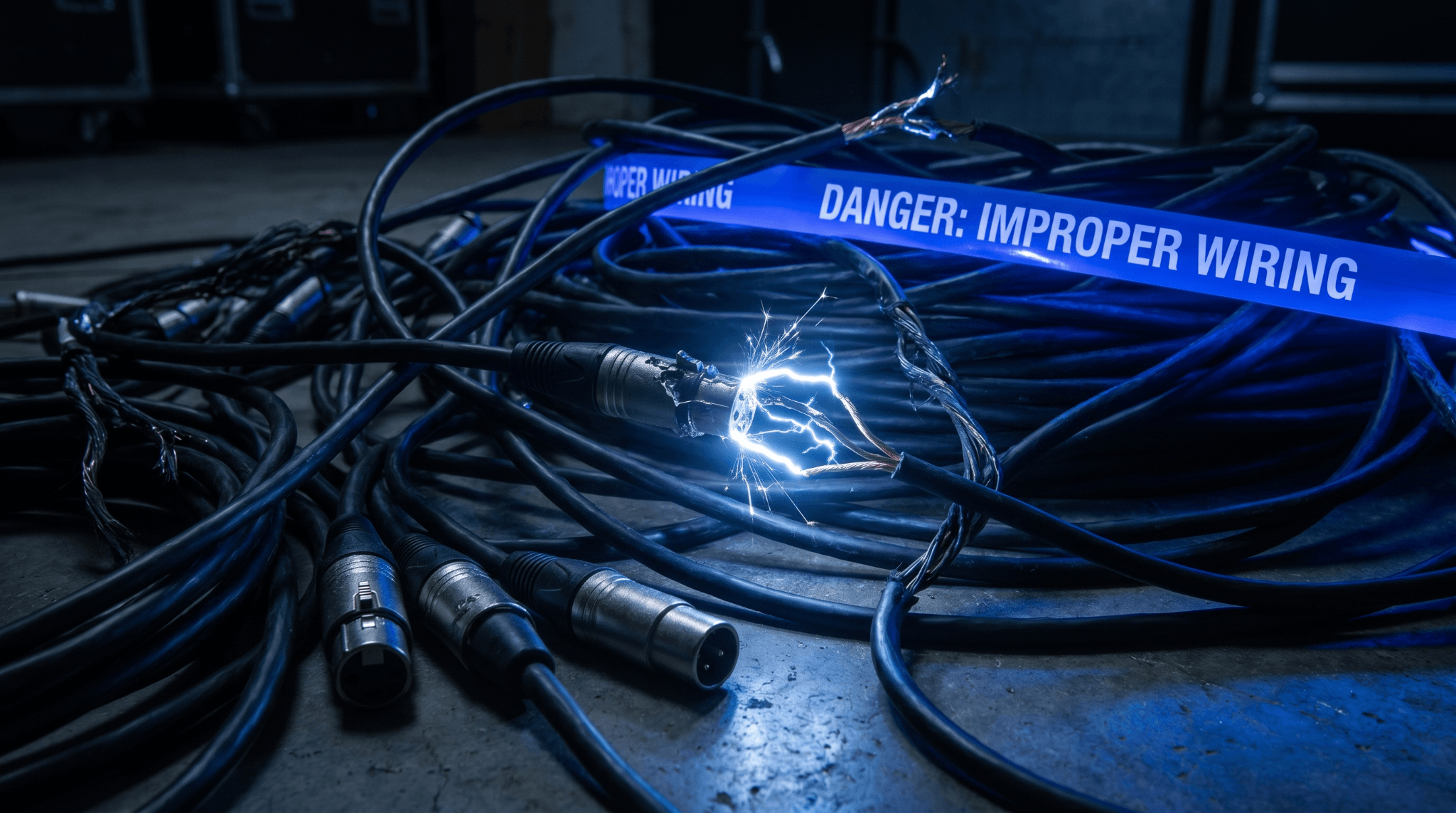
However, equipment damage can occur under specific system faults or improper operational practices:
- Miswired or Faulty XLR Cables: If an XLR cable has a short circuit between Pin 1 (ground) and either Pin 2 or Pin 3, the phantom power voltage becomes unbalanced. This sends a direct current voltage straight through the voice coil of a dynamic microphone or the output transformer of a passive device, which can quickly overheat and warp the delicate internal components.
- Unbalanced Audio Connections: Connecting an unbalanced device to a line with phantom power engaged can be highly damaging. In an unbalanced configuration, Pin 3 is typically shorted directly to the ground wire (Pin 1). This forces the full 48-volt current from Pin 2 to rush through the output stage of the connected device, which can destroy the output transistors of instruments like synthesizers, guitar effects processors, or consumer playback devices.
Impact of Active Voltage on Dynamic and Ribbon Microphones
Passive moving-coil dynamic microphones are robust and naturally immune to damage from properly implemented phantom power. However, vintage passive ribbon microphones require extreme caution.
A passive ribbon microphone uses an ultra-thin, highly fragile strip of aluminum suspended inside a strong magnetic field. If phantom power is applied via a properly functioning, perfectly balanced XLR cable, the ribbon element is safe.
The primary danger to ribbon microphones occurs during hot-plugging, which means connecting or disconnecting the microphone while the phantom power source is actively turned on.
This risk is amplified when routing connections through a TRS (Tip-Ring-Sleeve) patch bay. As a TRS jack is plugged in, the physical contacts slide across the internal pins sequentially rather than all at once. This creates a temporary short circuit, sending a massive surge of direct current through one side of the ribbon element. This sudden electrical surge causes the fragile ribbon to violently snap out of its magnetic gap, permanently stretching or destroying the element instantly.
Verification Procedures for Measuring Voltage
To ensure a studio setup is safe and operating within proper specifications, engineers should routinely verify the performance of their phantom power supplies using a high-precision digital multimeter.
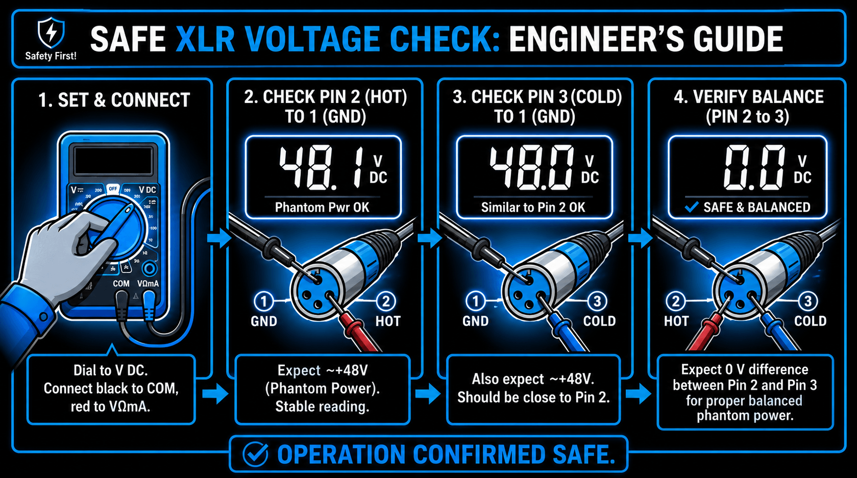
Operational Step-by-Step Verification Protocol
- Set the digital multimeter to read Direct Current Voltage (DC V).
- Disconnect the microphone cable from the transducer, leaving it connected to the audio interface or preamplifier with the 48V phantom power switch engaged.
- Place the black negative test probe of the multimeter into contact with Pin 1 (the ground socket) of the female XLR connector end.
- Insert the red positive test probe into Pin 2 (the positive signal socket). The multimeter should display a reading between +44 and +48 Volts DC.
- Move the red positive test probe to Pin 3 (the negative signal socket), keeping the black probe on Pin 1. The multimeter must display an identical voltage reading.
- Measure the voltage directly between Pin 2 and Pin 3. The resulting reading must be 0.00 Volts DC. Any measurable voltage difference here indicates an electrical imbalance in the resistors or a fault in the cable, either of which can distort audio or damage passive microphones.
Comprehensive Troubleshooting Guide for Phantom Power Issues
Diagnosing Signal Failures and Silent Captures
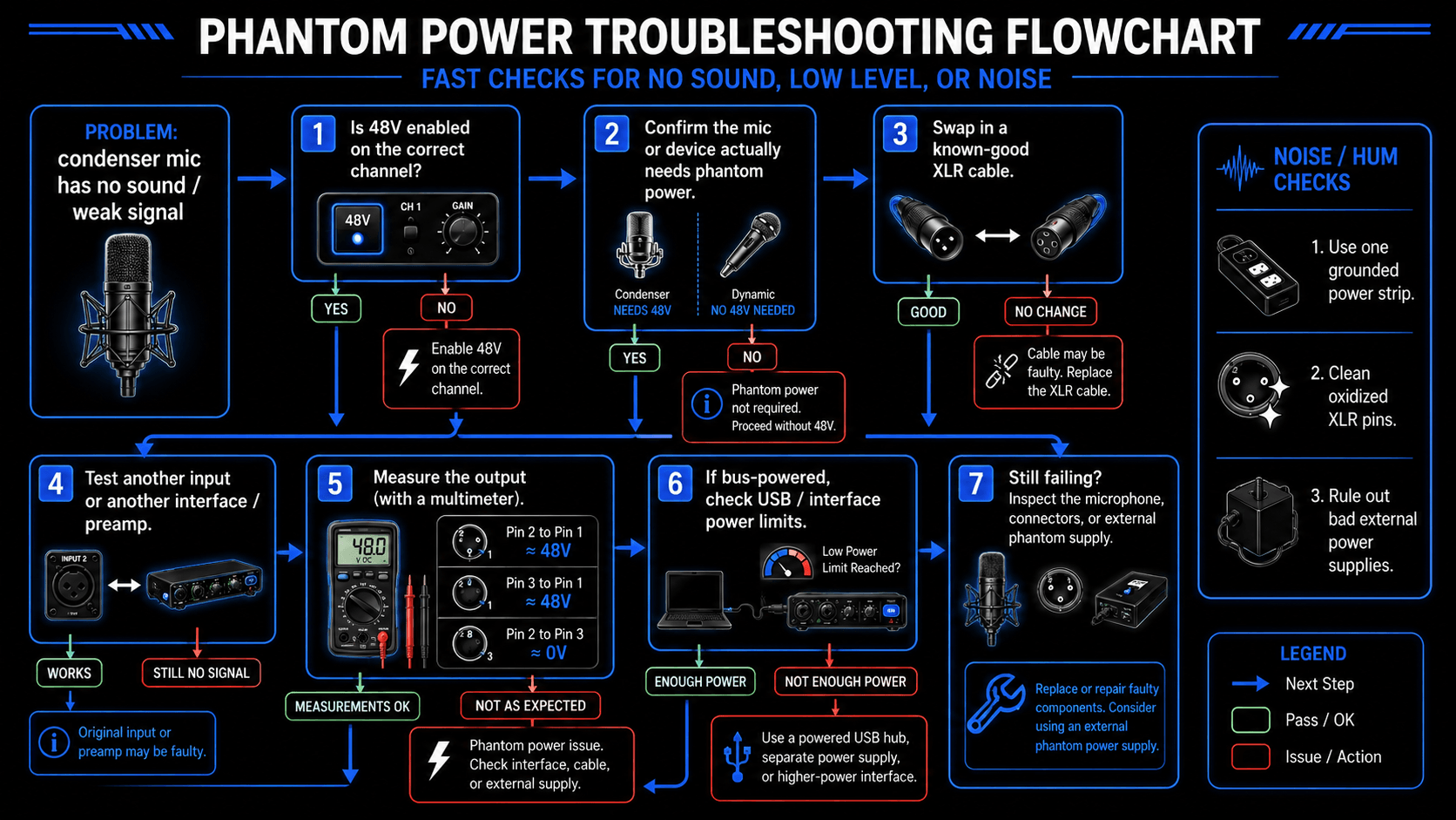
When a condenser microphone fails to output any audio signal, follow this diagnostic framework to locate and fix the power distribution failure:
- Verify Master Power Switches: Ensure the specific 48V activation button or software toggle is engaged for that exact input channel. Some entry-level mixing consoles use a single global switch that controls multiple channels at once, while others feature dedicated switches for each individual input.
- Inspect Cable Line Integrity: Swap out the existing XLR cable with a known, fully functional replacement. Phantom power cannot travel through cables with broken internal ground connections (Pin 1) or severed signal lines, even if the cable still manages to pass low-level audio from a passive dynamic microphone.
- Evaluate Power Constraints: When using multiple high-current condenser microphones with a bus-powered USB interface, the total power demand can exceed the maximum current output of the computer USB port. To fix this, connect the audio interface to an external mains power adapter or route the signal through a mains-powered USB hub.
Identifying and Eliminating Noise, Hum, and Interference
If engaging the phantom power system introduces unwanted background noise, low-frequency hum, or high-frequency buzzing into the audio chain, use the following steps to isolate the source of the problem:
- Isolate Ground Loop Hum: A loud 60Hz or 50Hz hum often points to a ground loop within the studio power system. Ensure that the audio interface, computer, and monitors are all connected to a single, properly grounded power distribution strip.
- Filter Out Power Supply Ripple: Low-quality or aging external power supplies can leak alternating current ripple into the 48-volt DC power rail. This electrical noise gets picked up by the microphone internal amplifier, creating an audible buzz. Testing the system with a high-quality external power conditioning unit can confirm this issue.
- Eliminate Contact Resistance Noise: Over time, oxidation and dirt can build up on the gold or silver pins of XLR connectors, creating uneven resistance across the lines. This asymmetry degrades the common-mode rejection of the system, turning quiet DC power into audible crackling or hissing noise. Clean the connectors thoroughly using a specialized electronic contact cleaner.
Step-by-Step Hardware Diagnostics
If the issue persists after preliminary checks, follow this systematic hardware checklist to isolate the failed component:
- Test the Preamplifier Isolation: Disconnect the XLR cable entirely from the input jack of the audio interface. Measure the raw voltage output directly at the interface panel pins. If the reading drops below 44 volts with no load attached, the internal voltage regulation circuit of the interface has failed.
- Verify Cable Shield Resistance: Use the multimeter resistance setting (Ohms) to check the XLR cable. Measure the resistance of Pin 1 from end to end. If the reading shows high resistance or an open circuit, the ground shield is broken, preventing the phantom power current from returning to its source.
- Inspect the Microphone Internal Circuitry: If the preamp and cable test perfectly but the microphone remains silent or noisy, open the microphone body chassis to inspect the internal components. Look closely for leaky capacitors, tarnished circuit board traces, or loose wiring connections at the base of the XLR pins.
Frequently Asked Questions
Can phantom power cause an electrical shock to a user?
The 48-volt current used in standard phantom power systems does not pose a dangerous electrical shock hazard to humans. Because the human body has high natural skin resistance, a 48-volt DC current cannot deliver enough current to cause physical harm or injury. At most, touching a damaged or exposed wire might cause a faint, mild tingling sensation.
Is it safe to connect an acoustic guitar preamp or keyboard line output to a channel with phantom power turned on?
Connecting line-level instruments directly to an XLR input with active 48V phantom power is highly discouraged. The high DC voltage can easily feed back into the output stage of keyboards, guitar preamps, or multi-effects processors, overheating and damaging their output transistors or operational amplifiers. Always use a passive DI box to safely connect these instruments, or ensure that phantom power is completely turned off before plugging them into a combination XLR-TRS input jack.
Why do some condenser microphones function without phantom power?
Certain condenser microphones do not require phantom power because they utilize an alternative internal power design. For example, electret microphones can run on a small internal battery cell, while vintage-style tube condenser microphones rely on a dedicated multi-pin cable connected to a large external power supply unit to handle their high voltage needs.
What is the functional difference between phantom power and T-power?
Phantom power and T-power (A-B power) are completely different and incompatible power delivery methods. Phantom power applies a matching positive voltage across Pin 2 and Pin 3 relative to the ground wire (Pin 1). T-power, which is an obsolete standard occasionally found on vintage film equipment, applies a 12-volt potential difference directly across the two signal lines (Pin 2 and Pin 3).
Does turning on phantom power increase the background noise floor of dynamic microphones?
In a properly wired, balanced audio system, engaging phantom power has absolutely no effect on the noise floor or performance of a passive dynamic microphone. Because the voltage is applied equally to both signal lines, no current flows through the microphone voice coil, keeping it completely silent and unaffected.
Can phantom power be transmitted over standard TRS patch cables?
Yes, phantom power can travel safely over balanced TRS (Tip-Ring-Sleeve) cables, where the Tip aligns with Pin 2, the Ring aligns with Pin 3, and the Sleeve aligns with Pin 1. However, using TRS cables at a patch bay introduces a significant risk.
As a TRS plug is inserted or removed, its physical contacts temporarily short circuit the internal connections. If phantom power is left turned on during this process, these short circuits can send damaging voltage surges into passive ribbon microphones or active line-level outputs.
What happens if two different power sources send phantom power to the same microphone at the same time?
If a microphone is connected to two preamps simultaneously through a passive splitter cable with phantom power turned on at both ends, the two voltages do not combine to create a dangerous 96-volt charge.
However, because the two power supplies are linked in parallel, they can alter the effective resistance of the circuit. This change can overload the current distribution, leading to increased audio distortion, reduced headroom, and unwanted ground loop hum between the two devices. To prevent this, always turn off phantom power on one of the preamps, or use a transformer-isolated microphone splitter